
Why a Dimmer Switch Three Way Setup Can Transform Your Home's Lighting
A dimmer switch three way setup lets you control the brightness of a light from two different locations — for example, at both ends of a staircase or hallway. Here's a quick summary of what you need to know:
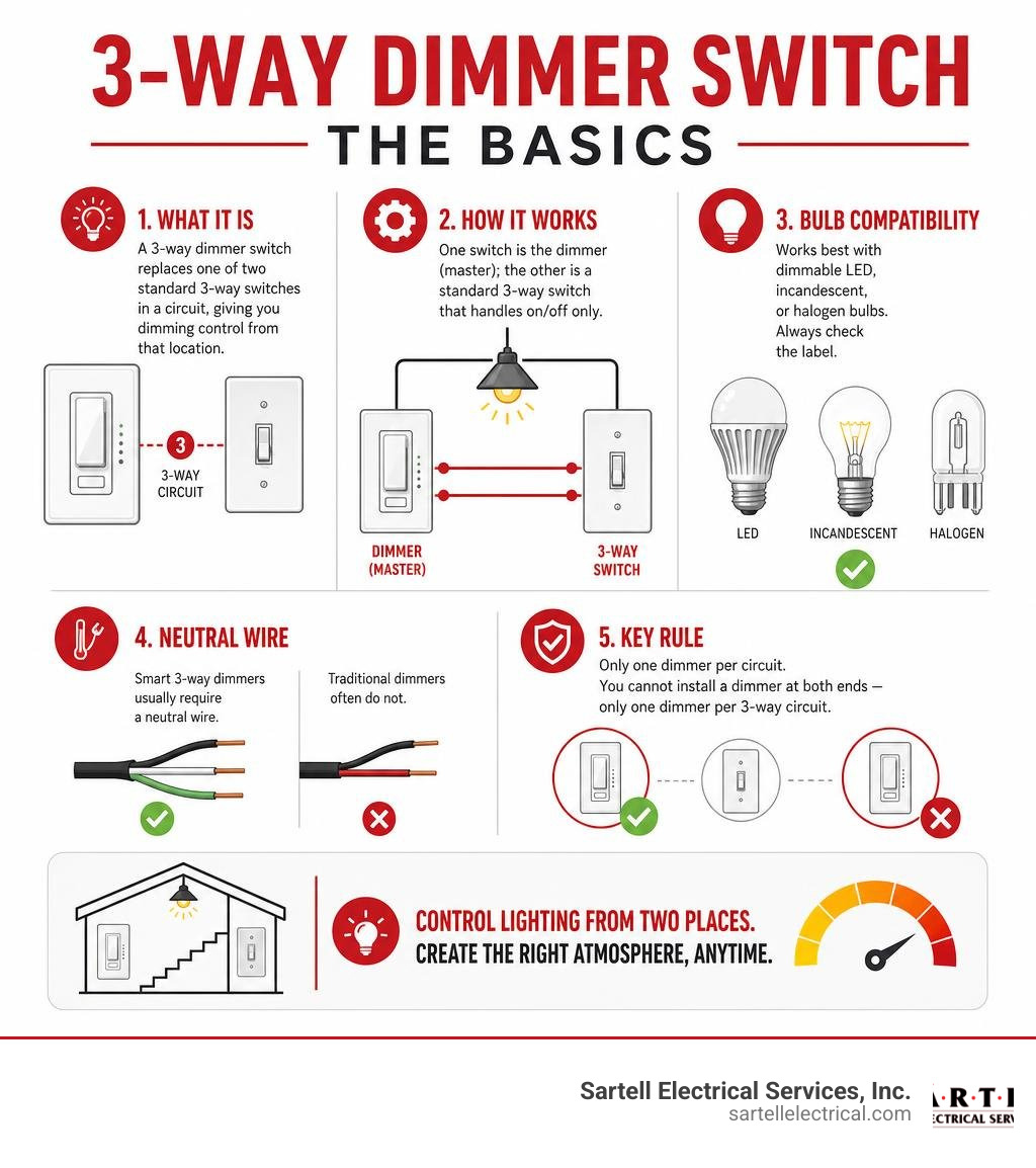
- What it is: A 3-way dimmer switch replaces one of two standard 3-way switches in a circuit, giving you dimming control from that location.
- How it works: One switch is the dimmer (master); the other is a standard 3-way switch that handles on/off only.
- Bulb compatibility: Works best with dimmable LED, incandescent, or halogen bulbs. Always check the label.
- Neutral wire: Smart 3-way dimmers usually require a neutral wire. Traditional dimmers often do not.
- Only one dimmer per circuit: You cannot install a dimmer at both ends — only one dimmer per 3-way circuit.
Getting this wrong is a common and frustrating mistake. The good news is that once you understand how 3-way dimmer circuits are set up, choosing and installing the right switch becomes much more straightforward.
Multi-location dimming is one of the most requested upgrades we see in both residential and commercial spaces — and for good reason. It adds convenience, improves ambiance, and can reduce energy use when paired with the right LED bulbs.
I'm Ed Sartell, President of Sartell Electrical Services, and I've been installing and troubleshooting dimmer switch three way circuits across Massachusetts since 1985. In that time, I've seen nearly every wiring configuration and compatibility challenge imaginable, so I'll walk you through everything you need to know to get this right.
Understanding the Dimmer Switch Three Way Setup
To understand a dimmer switch three way system, we first need to look at how multi-location lighting operates. In a standard home, a single-pole switch controls a light fixture from one wall location. It has two brass terminal screws (plus a green ground screw) and simply opens or closes the electrical pathway.
A three-way circuit is entirely different. It is designed to control a light fixture from two distinct locations. To do this, a three-way circuit requires two three-way switches. Each of these switches has three terminal screws (excluding the ground screw):
- One common terminal (usually a dark, oxidized copper or black screw).
- Two traveler terminals (typically brass or lighter-colored screws).
The traveler terminals connect the two switches together via a pair of "traveler wires" (usually running within a 3-conductor cable containing black, red, white, and bare copper wires). The common terminal on the first switch connects directly to the incoming hot wire from the circuit breaker panel (the "Line"). The common terminal on the second switch connects directly to the light fixture itself (the "Load").
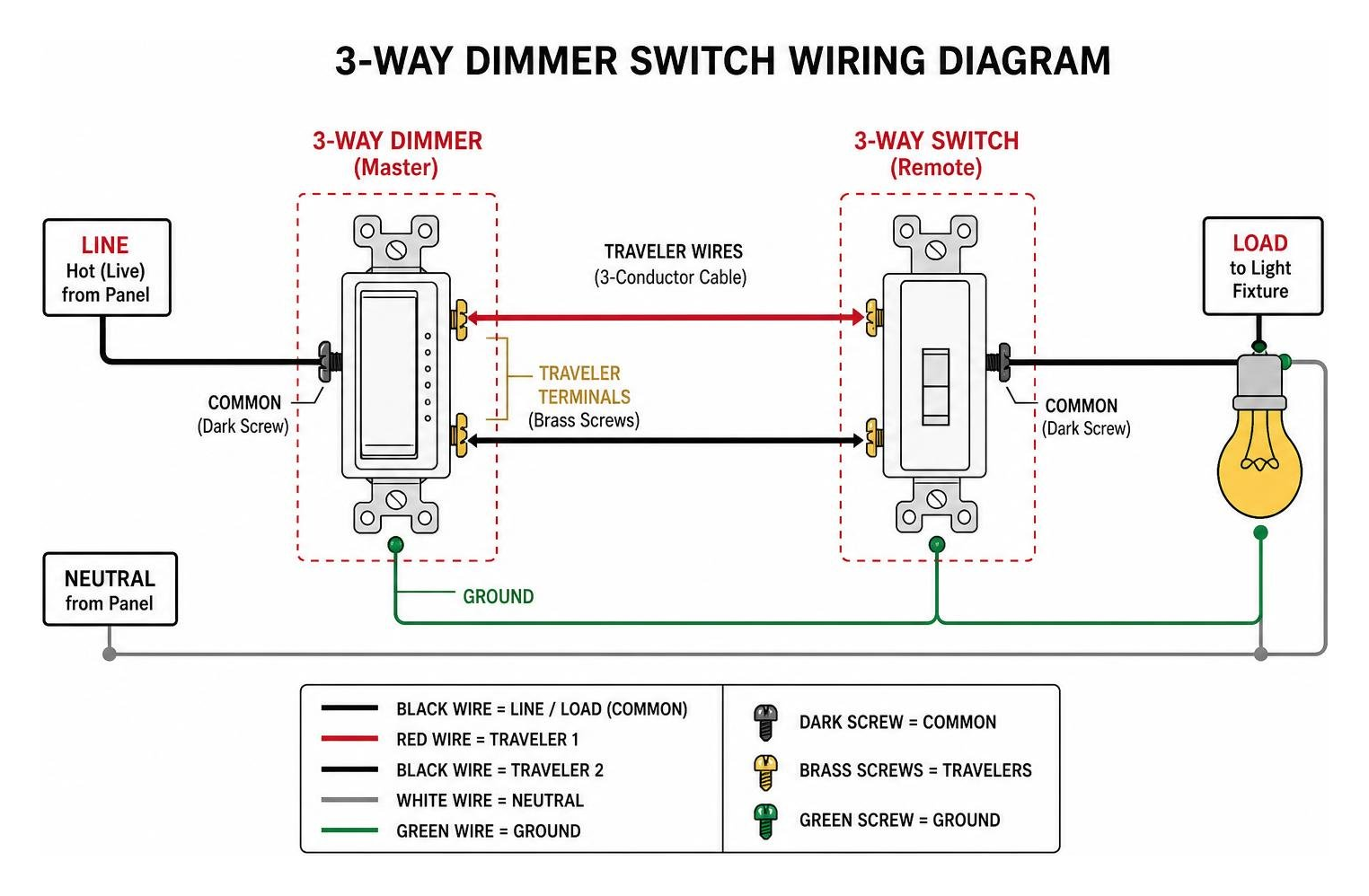
When you flip either switch, you redirect the electricity from one traveler wire to the other. If both switches are aligned to use the same traveler wire, the circuit closes, and the light turns on. If you flip either switch to the opposite position, the path breaks, and the light turns off.
So, where does a dimmer fit into this dance?
When adding dimming capabilities, homeowners often wonder: When installing a three way dimmer switch, does it matter which switch... is replaced? In a standard analog setup, you can replace either of the two three-way switches with a three-way dimmer. However, because of how electrical current is modulated to dim a light, you can only install one analog dimmer per circuit. The other switch must remain a standard, mechanical three-way toggle or rocker switch.
If you try to put two standard dimmers on the same 3-way circuit, they will fight for control of the voltage, causing severe flickering, buzzing, or complete circuit failure. If you want to know more about this limitation, check out our deep dive on Dimmer Duos: Can You Really Use Two Dimmers on One 3-Way Switch?.
Properly identifying the terminals on your existing switches is the absolute key to a successful installation. If you mix up the common wire with one of the traveler wires, your switches will behave erratically—for example, one switch might only work if the other switch is flipped to a specific position. For step-by-step help with terminal identification, read our guide on 3-Way Light Switch Terminals: How to Identify Common and Traveler Screws.
Key Features, Smart Tech, and Bulb Compatibility
Choosing a dimmer switch three way model in 2026 requires looking closely at bulb compatibility and dimming technologies. Gone are the days when every bulb was a simple incandescent wire filament. Today, we mix and match LED, CFL, and incandescent bulbs, which can lead to significant compatibility issues if you install the wrong hardware.
Traditional incandescent dimmers work by slicing out a portion of the AC voltage wave—a process known as forward-phase (or leading-edge) dimming. While this works beautifully for resistive loads like standard bulbs, it often wreaks havoc on the sensitive electronic drivers found in modern LED bulbs. LEDs prefer reverse-phase (or trailing-edge) dimming, which turns the current off at the end of the wave cycle rather than the beginning.
To solve this headache, top manufacturers have introduced "universal" dimmers. For instance, the radiant Tru-Universal Dimmer Switch | Legrand is designed to automatically calibrate itself to the specific load type connected to it. Whether you are running electronic low-voltage (ELV) drivers, dimmable LEDs, compact fluorescents, or old-school halogens, these advanced switches adjust their dimming phase to eliminate humming, buzzing, and flickering.
When shopping for a dimmer, you will also need to decide whether your home's wiring can support a neutral-wire switch or if you need a no-neutral solution. Most smart switches require a neutral wire to keep their internal Wi-Fi or Bluetooth radios powered when the lights are turned off. If you live in an older Massachusetts home built before the mid-1980s, your switch boxes might not have neutral wires. In those situations, you will need to look for specialized no-neutral dimmers. You can read more about these options in our guide, The No-Neutral Solution for Your 2-Wire Dimmer Switch.
| Bulb Type | Dimming Technology | Neutral Wire Required? | Key Characteristics |
|---|---|---|---|
| Incandescent / Halogen | Forward Phase (Leading Edge) | No | Warm glow, highly reliable, high power consumption |
| Dimmable LED | Reverse Phase (Trailing Edge) | Optional (Highly Recommended) | Energy-efficient, long life, prone to flickering on cheap dimmers |
| CFL (Compact Fluorescent) | Specialized Ballast | No | Slow start-up, limited dimming range (usually down to 10-20%) |
| Smart LED Bulbs | Internal App/Voice Control | Yes (at the switch if using smart switches) | Do not pair with standard wall dimmers; requires constant voltage |
Smart Home Integration and Voice Control
If you want to step into the future, a smart dimmer switch three way system is the way to go. Smart dimmers allow you to adjust your lighting via voice assistants like Amazon Alexa, Google Assistant, or Apple HomeKit, and set automated schedules using your smartphone.
Unlike traditional analog setups where you are strictly limited to one dimmer per circuit, smart lighting ecosystems offer a workaround. With systems like Lutron Caséta or Maestro, you install a "master" smart dimmer at one end of the 3-way circuit and pair it with wireless remotes (like Pico remotes) or specialized "companion" switches at the other locations. This configuration allows you to dim and brighten your lights from both ends of the room. For installation tips on these advanced systems, consult the Maestro LED Dimmer 3-Way 4-Way Install Tips documentation.

Additionally, modern smart switches often utilize Wi-Fi mesh technology, which allows multiple switches to communicate directly with one another. This means you can create "scenes"—for example, pressing a button on your hallway dimmer can simultaneously dim your living room lights, turn on your reading lamp, and lock your smart doors.
Troubleshooting Common Dimming Issues
Even with high-quality components, you may occasionally run into issues with your dimmer switch three way setup. Here are the most common problems we encounter in Middlesex and Essex counties, along with how to fix them:
- Flickering or Strobing: This usually happens when non-dimmable LED bulbs are paired with a dimmer switch, or when the total wattage of your LED bulbs is below the dimmer's minimum load requirement. Replacing the bulbs with high-quality, dimmable LEDs or adjusting the dimmer's low-end trim usually solves this.
- Buzzing or Humming: This is a classic symptom of voltage mismatch. If you hear a physical buzz coming from your light fixture or the wall switch, your dimmer is likely using forward-phase dimming on a bulb that requires reverse-phase dimming. Upgrading to a universal dimmer like Legrand’s Tru-Universal line will stop the noise.
- The "Pop-On" or Delay: Sometimes, when you slide a dimmer up from the off position, the lights remain dark until the slider is halfway up, at which point they suddenly burst onto a bright setting. This delay can be corrected by adjusting the high-end and low-end trim settings on your switch. Many modern dimmers have a small physical dial or a programming sequence to set these limits.
- The Ghost Glow: If your LED bulbs emit a faint glow even when the switch is turned completely off, there is likely a small amount of leakage current running through the circuit. This is common in smart switches that do not use a neutral wire, as they must trickle a tiny amount of power through the load to keep their internal Wi-Fi radios active. Installing a lutron LUT-MLC capacitor at the light fixture or switching to a neutral-required dimmer will eliminate the ghost glow.
If you are struggling to get your wiring sorted out, take a look at our comprehensive guide on Dimmer Switch Wiring for more troubleshooting tips.
Wiring and Installation Guide
Before you pick up a screwdriver, let's talk about safety. Working with electricity carries inherent risks. Always turn off the power at the main circuit breaker panel before touching any wires. Never rely solely on the wall switch to turn off the power; always use a reliable, non-contact voltage tester to verify that the wires inside the gang box are completely dead.
If you want a complete, professional overview of the process before starting, read our guide on Wiring Wonders: Installing Your 3-Way Dimmer Switch Like a Pro or watch this helpful video tutorial on How to Install a 3-Way Dimmer Switch (In Under 6 Minutes!) - YouTube.
To complete this installation, you will need a few basic tools:
- Non-contact voltage tester
- Flathead and Phillips screwdrivers
- Wire strippers/cutters
- Electrical tape
- Wire nuts (wire connectors)
- Utility knife (for carefully stripping outer cable jackets)
Step-by-Step Dimmer Switch Three Way Installation
Once you have gathered your tools and verified that the power is off, follow these steps to install your new dimmer switch three way:
- Remove the Old Switch: Unscrew the faceplate and the mounting screws holding the existing three-way switch in the wall box. Carefully pull the switch out, keeping the wires attached.
- Identify the Common Wire: Look closely at the existing switch. Locate the screw terminal that is a different color than the others (usually black or dark copper). This is your common terminal. Mark the wire attached to this screw with a piece of black electrical tape. The other two wires are your travelers.
- Disconnect the Wires: Unscrew the terminals and disconnect the old switch completely.
- Wire the New Dimmer: Take your new three-way dimmer switch. Connect the green (or bare copper) ground wire to the ground wire in your wall box. Next, connect the marked common wire to the common terminal on your dimmer (often labeled "COM" or marked by a black screw).
- Connect the Travelers: Connect the two remaining traveler wires to the two traveler terminals on the dimmer. In a standard 3-way circuit, it does not matter which traveler wire goes to which traveler terminal.
- Secure and Test: Carefully fold the wires back into the gang box, mount the switch with the screws, and attach the faceplate. Turn the circuit breaker back on and test the operation from both switch locations.

For advanced wiring diagrams and alternative physical placements (such as installing a smart module), refer to the 3-way wiring installation for Dimmer Switch - Aeotec Help Desk support page.
Identifying Wires for Your Dimmer Switch Three Way
One of the trickiest parts of this process is identifying wires when the colors in your wall box do not match standard diagrams. In the United States, standard residential wiring typically uses:
- Black: Hot (Line) or Load
- White: Neutral (though in 3-way switch loops, white is sometimes used as a traveler or hot wire—always verify!)
- Red: Traveler
- Bare Copper or Green: Ground
However, older homes in towns like Reading, Arlington, or Medford may have non-standard wiring colors or complex switch loops. The most reliable way to identify your wires is by using a voltage tester. With the power safely off, separate the wires so they are not touching. Turn the breaker back on temporarily and use your tester to see which wire is carrying live voltage. This live wire is your "Line" (incoming hot) and will connect to your first switch's common terminal.
For a complete breakdown of switch loop physics and wire identification, check out Wiring Made Easy: The 3-Way Switch Hook-Up Diagram Every Homeowner Needs.
Frequently Asked Questions about 3-Way Dimmers
Do 3-way dimmer switches require a neutral wire?
It depends on the type of dimmer you choose. Traditional analog toggle or slide dimmers do not require a neutral wire. They simply interrupt the hot path to modulate voltage. However, modern smart dimmers that connect to Wi-Fi, Zigbee, or Bluetooth usually require a neutral wire to keep their internal processors powered when the lights are off. If your home was built before 1985 and has not been rewired, you may need to look for specialized "no-neutral" smart switches. For a detailed breakdown of your options, read The No-Neutral Solution for Your 2-Wire Dimmer Switch.
Can you put two dimmer switches on a 3-way circuit?
No, you cannot put two standard analog dimmer switches on a single three-way circuit. If you attempt to do so, the two dimmers will interfere with each other's voltage regulation, resulting in rapid flickering, buzzing, or a complete failure to turn on. You must use one dimmer paired with a standard mechanical 3-way switch. If you want dimming control from both locations, you must purchase a specialized smart dimmer system that utilizes a "master" dimmer at one end and a digital "companion" switch or wireless remote at the other. Learn more in our article, Dimmer Duos: Can You Really Use Two Dimmers on One 3-Way Switch?.
Why are my LED lights flickering on a 3-way dimmer?
Flickering is almost always caused by a compatibility issue between the LED bulb's internal driver and the dimmer switch's circuitry. Many older dimmers were designed exclusively for high-wattage incandescent loads and cannot properly regulate the low wattage drawn by modern LEDs. To fix this, make sure your bulbs are explicitly labeled "dimmable" and that you are using an LED-compatible dimmer. Many advanced switches, such as the Toggle LED Advanced Dimmer Light Switch| Single Pole 3-Way, feature built-in trim adjustment dials that let you raise the minimum voltage level to eliminate low-end flickering.
Conclusion
Upgrading to a dimmer switch three way system is a fantastic way to enhance your home's comfort, save on energy bills, and set the perfect mood in any room. However, dealing with older wiring, identifying traveler lines, and ensuring smart home compatibility can quickly turn a quick DIY afternoon into a frustrating, head-scratching weekend.
If you are located in Middlesex County, Essex County, Norfolk County, Suffolk County, or anywhere in the Greater Boston area, you do not have to tackle this alone. At Sartell Electrical Services, Inc., we have spent over 30 years helping homeowners solve complex wiring puzzles safely and efficiently. Whether you need help swapping out a single switch or designing a whole-home smart lighting layout, our team of licensed, local professionals is here to help.
Ready to upgrade your home’s lighting without the hassle? Contact us today to schedule your professional 3-Way Dimmer Switch Install and let us handle the wiring wonders for you!
Why Choosing the Right All Electric Services Contractor Matters
All electric services cover a wide range of work — from wiring and panel upgrades to EV charger installations, generators, LED retrofits, and large-scale industrial projects. Finding the right contractor to handle that work reliably, safely, and on budget is where most businesses and institutions run into trouble.
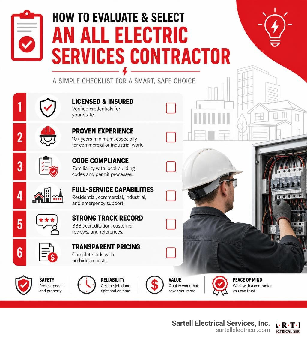
Quick answer — what to look for in an all electric services contractor:
- Licensed and insured — verified credentials for your state
- Proven experience — 10+ years minimum, especially for commercial or industrial scopes
- Code compliance — familiarity with local building codes and permit processes
- Full-service capabilities — residential, commercial, industrial, and emergency support
- Strong track record — BBB accreditation, customer reviews, and references
- Transparent pricing — complete bids with no hidden costs
This guide walks you through what professional electrical services should include, which upgrades matter most, how to evaluate contractors, and what questions to ask before signing anything.
Older electrical systems — especially in buildings constructed decades ago — were simply not designed to handle today's high-demand appliances, HVAC equipment, or EV charging loads. Ignoring the warning signs (flickering lights, warm outlets, frequently tripped breakers) isn't just inconvenient. It's a fire and safety risk.
Choosing the wrong contractor makes it worse. Missed deadlines, blown budgets, and code violations can derail a project entirely — particularly for commercial, industrial, or healthcare facilities where downtime has real consequences.
I'm Ed Sartell, President of Sartell Electrical Services, Inc., and I've been delivering all electric services to homeowners, builders, and businesses across Massachusetts since 1985. Over nearly four decades, I've seen what separates a contractor who gets it right from one who creates bigger problems — and this guide is built on that experience.
All electric services word guide:
What to Expect from Professional Electrical Services
When you hire a premier electrical contractor, you should expect more than just technical skill. True professionalism is built on four core values: safety, integrity, quality, and value.
For us, these values are not just marketing slogans; they are embedded in our daily decision-making. Every project must be executed under the safest possible conditions, with pricing that reflects absolute honesty, craftsmanship that exceeds industry standards, and a final result that brings long-term value to your property. Whether you are managing a small residential repair or a massive industrial build-out, these standards keep your project on schedule and within budget.
Comprehensive Residential and Commercial Solutions
A full-service electrical contractor must have the versatility to handle both everyday home needs and complex business systems.
For homeowners, this means delivering reliable residential electrical services that protect your family and enhance your comfort. Our team handles everything from modern wiring and outlet installations to ceiling fans and comprehensive panel upgrades. We understand how older homes in Massachusetts—especially those in historic areas like Boston, Salem, and Concord—require delicate handling and specialized knowledge to bring outdated systems up to modern safety standards.
On the business side, commercial electrical services require a deep understanding of operational continuity and energy demands. We partner with retail spaces, offices, and municipal buildings to provide:
- Complete tenant build-outs and office renovations
- High-efficiency lighting design and installations
- Dedicated power circuits for heavy office equipment and servers
- Comprehensive electrical maintenance to prevent costly downtime
Specialized Industrial and Infrastructure Projects
Industrial environments demand a level of expertise that goes far beyond standard commercial work. These facilities operate on high-voltage systems and require heavy machinery connections that must run continuously without interruption.
Our specialized industrial electrical services are designed to meet these intense demands. We handle complex power distribution systems, heavy machinery hookups, and high mast lighting installations.
Furthermore, modern industrial contracting utilizes advanced technology to ensure safety and accuracy. For example, we use drone inspections to safely evaluate high-mast lighting and hard-to-reach utility structures before our crews begin physical work. This prevents safety hazards and ensures we have the exact parts needed before ascending. Whether it is airport runway lighting, rail yard retrofits, or high-security facilities, our industrial division has the training and equipment to deliver turnkey solutions.
Key Upgrades and Energy-Efficient Solutions
As energy costs rise and environmental regulations tighten in Massachusetts, property owners are looking for ways to reduce their carbon footprint and lower their utility bills. Upgrading your electrical systems is one of the most effective ways to achieve both goals.
Here is a quick list of essential electrical upgrades that offer the highest return on investment:
- Service Panel Upgrades: Replacing old panels to increase capacity and safety.
- EV Charging Stations: Installing Level 2 chargers for faster, safer home or commercial charging.
- Backup Generators: Securing reliable power during severe New England weather.
- LED Lighting Retrofits: Replacing energy-hungry fixtures with modern, low-wattage LEDs.
- Smart Automation: Integrating smart switches, thermostats, and timers to optimize power usage.
Advanced EV Charger and Generator Installations
With the massive shift toward electric vehicles, having a reliable charging solution at home or your place of business is no longer a luxury—it is a necessity. Standard household outlets (Level 1) can take days to charge a modern EV. Installing a dedicated Level 2 EV charging station requires professional installation to ensure your electrical panel can handle the load safely.
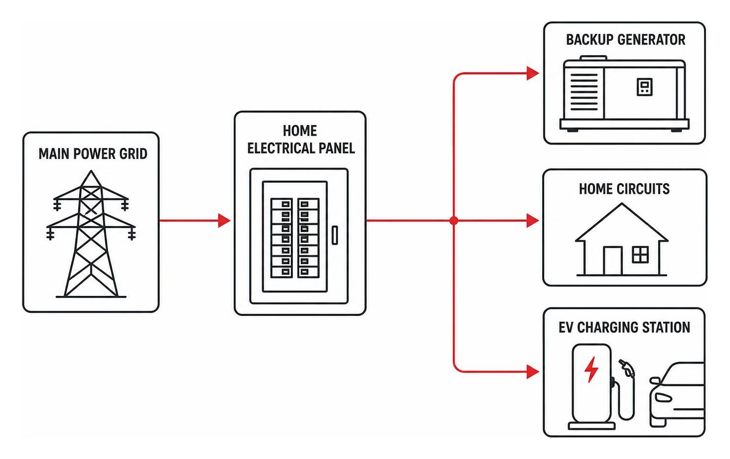
In addition to EV charging, New England winters and summer storms bring a constant threat of power outages. A professional generator installation ensures your home or business remains fully operational when the grid goes down. We specialize in standby backup generators that automatically kick on the moment utility power is lost, providing seamless storm preparedness for your family or commercial tenants.
LED Retrofits and Solar Energy Audits
Lighting accounts for a significant portion of any commercial or residential energy bill. Upgrading to LED lighting is one of the fastest ways to slash energy consumption. LED retrofits not only use up to 80% less energy than traditional incandescent or fluorescent bulbs, but they also last significantly longer, drastically reducing maintenance costs.
To maximize your savings, we recommend starting with comprehensive energy efficiency solutions such as energy audits. An audit pinpoints exactly where your property is losing power or using energy inefficiently. From there, we can design a custom retrofitting plan or assist with solar energy integrations to help you transition to sustainable, cost-effective power.
Ensuring Safety, Compliance, and Emergency Support

Electrical work is inherently dangerous. Attempting DIY repairs or hiring an unlicensed "handyman" is a recipe for code violations, system failures, and electrical fires. Professional contractors ensure that every wire, breaker, and fixture is installed in strict compliance with state and national safety standards.
Code Compliance and Safety Inspections
Every town in Massachusetts—from Reading and Andover to Quincy and Braintree—enforces specific local building codes alongside the National Electrical Code (NEC). Ensuring your property meets these standards is crucial for safety, insurance coverage, and future property sales.
We conduct thorough electrical safety checks to identify hidden hazards, such as:
- Outdated knob-and-tube or aluminum wiring
- Missing Ground Fault Circuit Interrupters (GFCIs) in wet areas like kitchens and bathrooms
- Overloaded circuits and improperly sized breakers
- Outdated panels that are known fire hazards
Our team handles the entire permitting process, ensuring all work is fully permitted, inspected, and approved by local municipal authorities.
24/7 Emergency Support and Rapid Response
Electrical emergencies do not wait for business hours. A fallen tree limb, a severe storm, or a sudden panel failure can leave your home or business in the dark at the worst possible moment.
That is why we offer reliable emergency electrical services backed by our rapid-response dispatch team. Our fully stocked service vehicles are ready 24/7 to handle critical issues like:
- Complete power outages
- Sparking panels or burning odors from outlets
- Storm-damaged service masts and meters
- Tripped main breakers that will not reset
When you need a 24-hour electrician services provider, you can count on our team to arrive quickly, diagnose the problem accurately, and restore safety and power to your property.
How to Choose the Best Contractor
Finding the right contractor to handle all electric services requires careful vetting. You want a team that combines technical expertise with outstanding customer service.
Key Considerations When Hiring for All Electric Services
When evaluating electrical contractors, always ask about their project management processes and safety records. A professional contractor should provide:
- Detailed, written estimates: Avoid vague verbal quotes. Insist on a line-item breakdown of materials, labor, and permit fees.
- Clear timelines: You should know exactly when the work will start and when it is expected to wrap up.
- Safety protocols: Ask how the team ensures on-site safety for both their workers and your property.
Evaluating Experience and Credentials for All Electric Services
Experience is the ultimate teacher in the electrical trade. A contractor with decades of local experience will understand the unique architectural styles and electrical challenges common to Massachusetts homes and commercial buildings.

Always verify the following credentials before hiring:
- Licensing: Ensure the contractor holds an active Massachusetts Master and Journeyman Electrician license.
- Insurance: The contractor must carry both general liability insurance and workers' compensation to protect you from liability in case of an accident.
- BBB Rating: Look for an A+ rating with the Better Business Bureau, which indicates a strong commitment to resolving customer issues.
- Background Checks: Ensure the company performs background checks on all technicians entering your home or business.
Assessing Customer Reviews and Professionalism
Online reviews on platforms like Google and Yelp offer valuable insight into a company's daily operations. Look for consistent praise regarding communication, reliability, and cleanliness.
A truly professional team respects your property. Technicians should wear shoe covers, use protective floor tarps, and leave their work areas cleaner than they found them. Furthermore, courtesy calls before arrival and clear follow-up communication after the job is completed are hallmarks of a customer-first business.
To help you understand the value of hiring a professional, here is a comparison of professional contractors versus the risks of DIY attempts:
| Service Feature | Professional Contractor | DIY / Unlicensed Worker |
|---|---|---|
| Licensing & Permits | Fully licensed; handles all local municipal permits | No permits pulled; risks fines and insurance denial |
| Safety Standards | Adheres strictly to NEC and OSHA safety protocols | High risk of electrocution, shocks, or electrical fires |
| Warranty & Guarantees | Work is backed by written satisfaction guarantees | No warranty; you pay out of pocket to fix mistakes |
| Diagnostic Tools | Uses advanced thermal imaging and testing equipment | Relies on guesswork, which can lead to missed hazards |
| Property Protection | Fully insured; uses floor tarps and shoe covers | No liability coverage; potential for property damage |
Frequently Asked Questions about Electrical Contractors
When should I call a professional electrician?
You should call a licensed professional immediately if you notice flickering or dimming lights, warm or discolored wall outlets, frequently tripping circuit breakers, or a persistent burning smell near electrical devices. These are signs of overloaded circuits, loose connections, or failing equipment that could lead to an electrical fire if ignored.
What are the benefits of upgrading an outdated electrical panel?
Upgrading your panel increases your home's electrical capacity, allowing you to run modern high-demand appliances, HVAC systems, and EV chargers safely. It also improves overall safety by replacing worn-out components that fail to trip during an overload, ensuring your property remains fully compliant with the latest building codes. For a deeper dive, check out our electrical service upgrades complete guide.
How do electrical contractors handle emergency calls?
Reputable contractors provide 24/7 emergency dispatch. When you call with an urgent issue, a technician is dispatched in a fully stocked service vehicle to quickly troubleshoot the problem, isolate any immediate hazards to ensure your safety, and perform the necessary repairs to restore power as quickly as possible.
Conclusion
Your electrical system is the lifeblood of your property. Whether you are upgrading your home's panel, retrofitting a commercial warehouse with energy-efficient LEDs, or installing advanced EV charging infrastructure, the quality of the contractor you choose makes all the difference.
At Sartell Electrical Services, Inc., we have spent over 30 years building a reputation for excellence, safety, and unmatched customer service throughout Massachusetts. Based in Reading, MA, we proudly serve communities across Essex, Middlesex, Norfolk, and Suffolk Counties, including Greater Boston, Andover, Chelsea, and beyond.
Our experienced, background-checked, and fully licensed electricians are ready to handle projects of all sizes—from residential repairs to complex commercial, industrial, telecom, and healthcare electrical systems.
Ready to experience the difference that true professionalism makes? Contact us today to discuss your next project or request a detailed estimate through our Sartell Electrical Contractor Service portal. Let us keep your power running safely and efficiently!
How to Seamlessly Integrate Your Electrical Systems
What Is Electrical Systems Integration — and Why Does It Matter?
Electrical systems integration is the process of connecting and coordinating different electrical components and subsystems into one unified, efficient, and safe network.
Quick answer:
| Question | Answer |
|---|---|
| What is it? | Linking power, control, automation, and safety systems so they work together seamlessly |
| Who needs it? | Industrial facilities, commercial buildings, automotive/EV platforms, and more |
| Why does it matter? | Reduces energy waste, improves safety, cuts costs, and enables scalability |
| Key benefit | Optimized integration can reduce energy waste by up to 30% in industrial facilities |
| Main risk of skipping it | Inefficiency, safety hazards, compliance failures, and costly re-work |
Modern facilities and vehicles are no longer simple. A commercial building might run dozens of separate systems — lighting, HVAC, fire alarms, power distribution, automation — all from different manufacturers, installed at different times.
Without integration, those systems don't talk to each other. That means wasted energy, blind spots in monitoring, and serious safety risks.
With a well-executed integration strategy, everything works together. You get real-time visibility, smarter control, and a system that can grow with your operation.
I'm Ed Sartell, President of Sartell Electrical Services, and I've spent nearly four decades managing complex electrical systems integration projects across Massachusetts — from commercial builds to industrial facilities. In that time, I've seen how the right integration approach can transform a facility's safety, efficiency, and long-term reliability.
Handy electrical systems integration terms:
- electrical and instrumentation companies
- electrical & instrumentation
- industrial power distribution systems
The Core Principles of Electrical Systems Integration
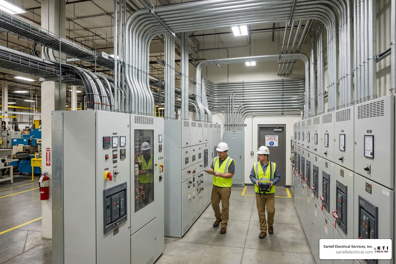
At its heart, electrical systems integration is about breaking down the walls between isolated systems. Think of a standard industrial facility: you have power distribution hardware supplying electricity, Programmable Logic Controllers (PLCs) managing machinery, and HVAC units keeping the environment stable.
When these operate as "islands of automation," they waste energy and increase maintenance overhead. Integrating them creates a cohesive, single-pane-of-glass environment where power quality analyzer data can trigger automated load-shedding commands, and HVAC systems adjust dynamically based on real-time production schedules.
According to industry data, implementing comprehensive electrical systems integration can reduce energy waste by up to 30% in industrial facilities. By optimizing power distribution and automation together, we eliminate redundant running times and minimize peak demand surcharges.
To achieve this level of optimization, you need a team that understands both high-power distribution and delicate digital controls. This is where partnering with Why Your Project Needs Electrical and Instrumentation Experts becomes vital for your project's success.
Traditional Wiring vs. Modern Multiplexed and Zonal Architectures
For decades, electrical systems relied on point-to-point wiring. If you needed to connect ten sensors to a central controller, you ran ten separate pairs of copper wires. In modern facilities and vehicles, this approach leads to incredibly heavy, complex, and fragile wiring harnesses.
Modern systems utilize multiplexed and zonal architectures to simplify physical runs and improve signal integrity.
| Feature | Traditional Point-to-Point Wiring | Modern Multiplexed / Zonal Architecture |
|---|---|---|
| Wiring Density | High; dedicated physical copper wire for every signal | Low; shared high-speed data buses (e.g., Automotive Ethernet, CAN bus) |
| Weight & Mass | Heavy; thick wire bundles increase structural loads | Light; minimized wiring mass and optimized routing |
| Scalability | Poor; adding new features requires pulling new wires | Excellent; new modules plug directly into the existing data backbone |
| Troubleshooting | Difficult; tracing broken connections through massive bundles | Simple; digital diagnostics identify exact module failures instantly |
| Signal Integrity | Vulnerable to electromagnetic interference (EMI) | High; shielded high-speed data protocols prevent data corruption |
By transitioning to a zonal architecture, we partition the system into localized zones. Each zone features its own local controller or remote power module that handles nearby devices and communicates back to the central processor via a high-speed data link. This drastically reduces wire weight, simplifies manufacturing, and ensures robust performance.
Key Benefits of Electrical Systems Integration for Modern Facilities
When you invest in a fully integrated electrical infrastructure, you are not just cleaning up your wiring closets; you are fundamentally upgrading your business's operational capabilities.
- Scalability: Integrated systems are modular. When you need to add a new production line, an EV charging station, or a solar array, you can plug them into your existing system architecture without starting from scratch.
- Enhanced Safety and Compliance: Real-time monitoring allows integrated systems to detect thermal overloads, ground faults, or phase imbalances before they trigger catastrophic failures.
- Long-Term Reliability: By reducing the physical point-to-point connections, you eliminate the most common failure points in any electrical system: physical splices and terminals.
- Advanced Performance Monitoring: Integration allows SCADA and HMI platforms to gather data from every corner of your facility, giving you actionable analytics on your energy consumption.
To explore how these benefits translate directly to your facility's bottom line, you can read more about our tailored Industrial Electrical Solutions.
Overcoming Common Challenges in Electrical Systems Integration
Integrating electrical systems is not without its hurdles. The most common obstacle we encounter is the presence of legacy equipment. Many facilities operate highly reliable machines built twenty or thirty years ago that lack modern communication ports.
To bridge this gap, we use industrial protocol gateways and intelligent electronic devices (IEDs). These tools translate older analog signals into modern digital protocols like Modbus, DNP3, or Ethernet/IP. By mapping these data points correctly, we break down information silos and bring your legacy hardware into the modern age without requiring expensive machinery replacements.
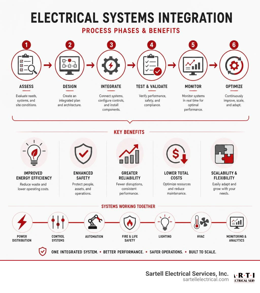
The 5 Key Phases of a Successful Integration Project

A successful integration project is never put together on the fly. It requires a rigorous, engineering-led process. At Sartell Electrical Services, we align our workflows with strict project management standards to ensure your system is optimized, safe, and delivered on schedule.
To understand how we keep complex projects on track, explore our approach to Electrical Project Management and Electrical Project Coordination.
Phase 1 & 2: Analysis, Strategic Planning, and Electrical System Design
The foundation of any integration project rests on these initial steps:
- Analysis & Strategic Planning: We begin with a comprehensive facility audit. We document all existing power distribution assets, assess network compatibility, and perform electrical loading surveys to establish an accurate baseline.
- Design & Documentation: Next, our engineers develop detailed schematics, blueprints, and data flows. We map out the physical routing, select component specifications, and design the system to meet your exact efficiency goals.
Proper planning during these phases prevents costly mid-project changes. Learn how we lay this groundwork by reading about our Electrical Pre-Construction Planning and our dedicated Electrical System Design services.
Phase 3, 4 & 5: Implementation, Commissioning, and Long-Term Maintenance
Once the designs are approved, we transition to physical integration:
- Implementation & Testing: Our field technicians install the physical infrastructure, route the cabling, and program the PLCs and HMIs. We conduct rigorous component-level testing to verify signal integrity before powering up the entire system.
- System Commissioning: During commissioning, we test the entire integrated network under real-world operating conditions. We verify safety functions, test fail-safes, and ensure 100% NEC compliance.
- Long-Term Maintenance & Reliability: Integrated systems require proactive care. We establish preventative maintenance schedules, perform thermal imaging, and run diagnostics to protect your investment and prevent unexpected downtime.
For an in-depth look at how we manage these field services, check out our Industrial Electrical Services Complete Guide.
Advanced Technologies: BCMs, RPMs, and Digital Twins
Modern integration projects leverage intelligent hardware and software to streamline power distribution and simplify control systems.
How Body Control Modules and Remote Power Modules Simplify Distribution
In both advanced vehicle platforms and complex industrial control panels, Body Control Modules (BCMs) and Remote Power Modules (RPMs) have replaced traditional fuse boxes and mechanical relays.
A BCM acts as a central computer hub, processing input signals from sensors and switches and transmitting commands across a multiplexed data link. When paired with Remote Power Modules, the physical wiring footprint drops drastically.
For example, a single RPM in a multiplexed system can control up to 80 amps of total current across six independent 20-amp outputs. Instead of routing heavy high-current wires from a dashboard switch all the way to an auxiliary load, you run a light, low-current data link to the RPM situated right next to the load. The RPM handles the heavy switching locally, reducing wiring weight, preventing voltage drops, and allowing software-defined circuit protection.
Leveraging ECAD Software and Digital Twins for Lifecycle Management
Designing these complex architectures by hand is a recipe for error. That is why modern integration relies on Electrical Computer-Aided Design (ECAD) software and digital twin technology.
A digital twin is a virtual, high-fidelity replica of your physical electrical system. By implementing a model-based electrical enterprise, design teams can simulate energy flows, test fault conditions, and verify logic before a single physical wire is cut.
Industry studies show that using these advanced design platforms can reduce design error probability by 25% and functional test time by 50%. The digital twin remains active throughout the system's life, serving as an invaluable troubleshooting tool for maintenance technicians. Platforms like the Capital Systems Integrator | Siemens enable us to maintain this digital thread from initial design all the way to active field servicing.
Safety, Compliance, and High-Voltage/Low-Voltage Integration
Integrating high-voltage (HV) power distribution with low-voltage (LV) control networks is one of the most critical safety challenges in modern electrical engineering. If high voltage leaks into your low-voltage communication lines, it will instantly destroy expensive control hardware and pose a lethal threat to operators.
Managing these risks requires a thorough understanding of system boundaries. For a complete guide on designing these robust systems safely, read our Power Distribution Systems Design Guide for Modern Industries.
Navigating NEC Standards and ISO 15288 Systems Engineering
All electrical integration work must strictly comply with the National Electrical Code (NEC) to ensure safety and maintain insurance eligibility. When we integrate complex power systems, we also utilize systems engineering frameworks like ISO 15288.
This standard ensures that safety functions, risk assessments, and Failure Modes and Effects Analyses (FMEA) are systematically applied throughout the project's lifecycle. For a deeper look into how professional engineering standards govern complex power system development, you can review the technical guidelines in Section 7 Power system development and integration.
Best Practices for Co-Locating High-Voltage and Low-Voltage Systems
When co-locating HV and LV systems inside the same enclosures or wireways, we follow strict isolation protocols:
- High-Voltage Interlock Loops (HVIL): We implement physical safety loops that automatically disconnect high-voltage power sources if an enclosure door is opened or a connector is unplugged.
- Active Discharge Circuits: These systems quickly discharge residual energy in high-capacity capacitors within seconds of a system shutdown.
- Shielding and Physical Isolation: Low-voltage data lines are routed through dedicated, shielded conduits to prevent electromagnetic interference from adjacent high-voltage lines.
- Single-Point Grounding: We establish clean, bare-metal ground connections sealed with anti-corrosion grease to prevent ground loops and shield noise.
These isolation techniques are particularly crucial in high-density environments like server farms. You can learn more about how we implement these standards in our Data Center Solutions Boston guide.
Frequently Asked Questions about Electrical Integration
How do I audit my existing facility for integration readiness?
A thorough pre-integration audit involves documenting every asset in your facility, including switchgear, panelboards, motor control centers, and existing automation controllers. We assess the physical space, check network compatibility (determining if your existing controllers can support modern Ethernet-based protocols), and review historical energy bills to pinpoint efficiency goals. Finally, we evaluate your 5-to-10-year facility growth plans to ensure the new integrated architecture is built to scale.
What are the main risks of poor electrical integration?
Poorly executed integration projects often suffer from operational downtime, signal corruption due to improper shielding, and frequent nuisance tripping of circuit breakers. In worst-case scenarios, failing to isolate high and low voltages can lead to catastrophic hardware destruction, electrical fires, and severe safety hazards for your staff.
How does systems integration support renewable energy like solar?
Integrating solar arrays, battery energy storage systems (BESS), and microgrids into your facility's main electrical system requires real-time control. Systems integration allows your facility to dynamically switch between grid power, solar generation, and battery storage based on real-time utility rates and current loads. This ensures grid stability, provides backup power during utility outages, and maximizes your return on investment in renewable energy.
Conclusion
Successfully executing an electrical systems integration project requires deep technical expertise, meticulous planning, and an unwavering commitment to safety. Whether you are upgrading an industrial manufacturing line, optimizing a commercial facility, or installing advanced low-voltage automation systems, the right integration partner makes all the difference.
At Sartell Electrical Services, Inc., we have spent over 30 years serving businesses throughout Massachusetts — including Reading, Boston, Middlesex County, Essex County, and the Greater Boston area. Our commitment to excellence, leadership, and outstanding customer service ensures that your project will be completed safely, on time, and to the highest standards.
Ready to optimize your facility's electrical infrastructure? Explore our Commercial Electrical Services or contact us today to Partner with Sartell Electrical Services on your next integration project.
What Is a 3 Pole Dimmer Switch — and Why Does It Matter?
A 3 pole dimmer switch (also called a 3-way dimmer) lets you control the same light fixture from two different locations — and adjust the brightness from either one.
Here's a quick breakdown:
| Feature | What It Means |
|---|---|
| Controls lights from | 2 separate locations (e.g., top and bottom of stairs) |
| Works with | LED, CFL, incandescent, and halogen bulbs |
| Requires neutral wire? | Not always — many models work without one |
| Smart options available? | Yes — Alexa, Google Assistant, SmartThings compatible |
| DIY-friendly? | Often yes, but always turn off power first |
Think staircases, hallways, large living rooms, or any space where you walk in from more than one entry point. A standard single-pole dimmer just won't cut it in those situations.
Upgrading to a 3-way dimmer gives you both convenience and control — from wherever you happen to be standing.
I'm Ed Sartell, President of Sartell Electrical Services, and I've been installing and troubleshooting 3 pole dimmer switch setups across Massachusetts since 1985. In this guide, I'll walk you through everything you need to know — from how they work to how to install one safely.
Demystifying the 3 Pole Dimmer Switch: How It Works
To understand a 3 pole dimmer switch, we first need to look at how electricity travels through your walls. In standard household wiring, a basic switch is like a simple drawbridge: it either connects the circuit (lights on) or breaks it (lights off).
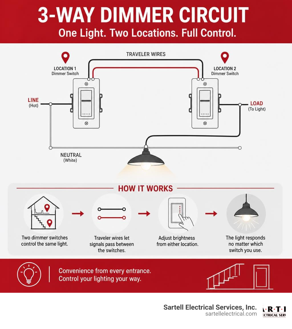
A 3-way circuit is more like a train track with a switching station. It allows you to redirect the flow of electricity so that toggling either switch in the circuit will change the state of the light.
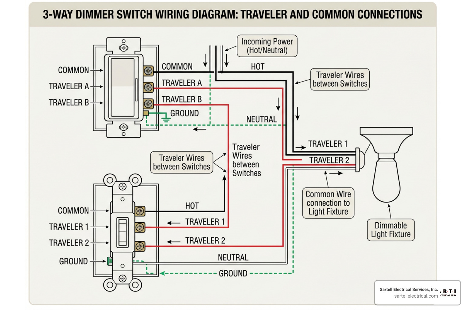
When we introduce a dimmer to this setup, we aren't just turning the power on and off; we are slicing the electrical current to reduce the amount of energy reaching the bulb. This rapid chopping of the electrical wave (happening up to 120 times per second!) is what creates the dimming effect.
To explore the fundamentals of how these systems are laid out, you can check out our detailed guide on Dimmer Switch Wiring and review an AC Dimmer Circuit Diagram to visualize the current flow.
Single-Pole vs. 3 Pole Dimmer Switch: Key Differences
The most common point of confusion for homeowners is choosing between a single-pole dimmer and a 3 pole dimmer switch. The difference comes down to the number of control points:
- Single-Pole Dimmer Switch: This is designed for single-point control. If your room has only one doorway and one switch that controls the overhead light, you need a single-pole dimmer. You can learn more about these in The Ultimate 1-Way Dimmer Switch Connection Manual.
- 3-Way (3-Pole) Dimmer Switch: This is engineered for dual-point control. If you have a staircase with a switch at the bottom and another at the top, or a long hallway with switches at both ends, you need a 3-way setup.
Fortunately, most modern dimmers sold on the market today are labeled as "Single-Pole/3-Way" universal models. This means they can be wired to work in either configuration, giving you great flexibility during installation.
The Role of Travelers and Common Wires
If you open up a standard single-pole switch box, you will typically find two main insulated wires (plus a bare ground wire). But a 3-way electrical box is a bit more crowded. It contains:
- The Common Terminal (and Wire): On one of the switches, this black screw connects to the hot wire coming directly from your electrical panel. On the other switch, the common terminal connects to the load wire going to the light fixture.
- Traveler Wires: These are two dedicated wires (usually red and black, running within the same Romex cable) that link the two switches together. They act as the alternate pathways for the electricity. When you flip switch A, it sends power down Traveler 1. If switch B is set to receive from Traveler 1, the light turns on. Flip switch B, and it switches its connection to Traveler 2, turning the light off.
Understanding this relationship is crucial when you are Wiring Wonders: Connecting Two Light Switches for Seamless Control to ensure the switches communicate properly without short-circuiting.
Choosing the Right Dimmer: Compatibility and Features
Not all dimmers are created equal, and choosing the wrong one can lead to buzzing, flickering, or even damaged bulbs. When shopping for a 3 Way Dimmer Switch - Amazon.com, you will find over 4,000 results. To narrow down your choices, you must understand bulb compatibility, wattage ratings, and safety certifications.
Here is a quick reference table to help you compare compatibility across different bulb types:
| Bulb Type | Dimming Technology Needed | Wattage Considerations | Common Issues |
|---|---|---|---|
| LED | Forward or Reverse Phase (LED+) | Very low (typically 150W max per dimmer) | Flickering, buzzing, narrow dimming range |
| CFL | Specifically rated dimmable CFL | Low wattage limits | Slow start-up, limited dimming span |
| Incandescent | Standard Triac / Forward Phase | High capacity (600W - 1000W) | Generates heat, uses more energy |
| Halogen | Standard Triac / Forward Phase | High capacity (600W - 1000W) | Runs very hot, shortens bulb life if dimmed too low |
Bulb Compatibility and Preventing Flicker
The transition to energy-efficient lighting has made dimmer selection slightly more complex. Older incandescent bulbs dimmed beautifully on simple analog switches. However, modern LEDs rely on internal drivers to manage power.
If you pair an older dimmer with a modern LED bulb, you will likely experience annoying flickering or buzzing. To prevent this, look for dimmers designed with advanced microprocessor controls.
For instance, the radiant Tru-Universal Dimmer Switch | Legrand and the TradeMaster® Tru-Universal Single Pole/3-Way Toggle Slide Dimmer, Preset, White | Dimmers | Light Switches and Dimmers | Wiring Devices are engineered to auto-calibrate. They detect the type of load connected (whether it is forward-phase or reverse-phase/ELV) and automatically adjust their minimum voltage levels to eliminate flicker entirely.
Additionally, pay attention to derating and heat sinks. When you install multiple dimmers side-by-side in a multi-gang wallbox, you often have to break off the metal side tabs (the heat sinks) to make them fit. Doing this reduces the switch's ability to dissipate heat, meaning you must lower (derate) the maximum wattage the switch can safely handle.
Do You Need a Neutral Wire?
One of the biggest hurdles in DIY electrical work is the presence—or absence—of a neutral wire.
Historically, light switches only needed to interrupt the hot wire, so older homes (built before the mid-1980s) often do not have neutral wires running to the switch boxes. However, modern smart dimmers require constant power to stay connected to your Wi-Fi network, which means they usually require a neutral wire to complete their own internal circuit.
If you live in an older Massachusetts home, don't panic. There are plenty of mechanical and specialized smart dimmers that do not require a neutral wire. You can read more about your options in The No-Neutral Solution for Your 2-Wire Dimmer Switch.
Top-Rated 3-Way Dimmer Switches on the Market
Upgrading your home's lighting doesn't have to break the bank. Depending on your goals—whether you want a budget-friendly swap, a smart home upgrade, or a high-end designer look—there is a perfect 3 pole dimmer switch for your project.

Smart Dimmers and Voice Assistant Integration
For those looking to step into home automation, smart 3-way dimmers are incredibly popular. Brands like Kasa Smart offer kits that make multi-location smart dimming seamless. Their 3-Way Dimmer Switch Kit is highly rated on Amazon, with thousands of units bought every month. These switches connect directly to your 2.4GHz Wi-Fi network and integrate beautifully with Alexa, Google Assistant, and SmartThings.
Another excellent heavy-duty option is the Lutron Maestro Dimmer Switch for Incandescent and Halogen, 1000 ... , which provides multi-location dimming using companion controllers. This allows you to smoothly adjust the lights from up to ten different locations in a single circuit!
Premium and Aesthetic Dimmer Options
If you are renovating a historic home in Boston or simply want a tactile, luxurious feel on your walls, standard plastic switches might not cut it. Premium design collections offer stunning alternatives:
- Polished Nickel and Antique Brass: The Kew Triple 3x Dimmer Switch Polished Nickel | Switches & Dimmers provides an elegant, warm metallic finish that is far more versatile than standard chrome. For a more traditional look, you can opt for the Kew Triple 3x Dimmer Switch Antique Brass | Switches & Dimmers , which features a "living finish" that beautifully patinates over time.
- Minimalist Flush Designs: If you want your controls to blend seamlessly into your plaster or brick walls, options like the Kew Triple 3x Vertical Dimmer Switch Clear Polished Nickel | Switches & Dimmers feature transparent polycarbonate plates that let your wallpaper or paint color show through.
- Touch and Multi-Way Systems: For a ultra-modern touch interface, the Varilight Value Polar White 3 Gang 0-100W Multi-Way Touch Master LED Dimmer with Polished Chrome Buttons | UKES combines sophisticated micro-touch buttons with companion controllers to give you precise dimming across multi-gang setups.
How to Install a 3-Way Dimmer Safely
Working with electricity can feel intimidating, but with the right preparation and safety precautions, installing a 3 pole dimmer switch is a highly achievable weekend project.
Before you begin, watch this quick visual demonstration on How to Install a 3-Way Dimmer Switch (In Under 6 Minutes!) - YouTube to familiarize yourself with the physical process.
Step-by-Step Guide to Installing a 3 Pole Dimmer Switch
If you are ready to tackle the installation, follow these clear steps:
- Shut Off the Power: Go to your main electrical panel and switch off the breaker controlling the circuit.
- Verify the Power is Off: Use a non-contact voltage tester inside the switch box. Test all wires to ensure there is absolutely no active electrical current before touching anything.
- Document the Existing Setup: Unscrew the old switch from the wall and pull it out gently. Before disconnecting any wires, take a clear photo of the connections on your phone.
- Identify and Label the Common Wire: Look closely at your old switch. One of the screw terminals will be a different color than the others (usually black or labeled "COM"). Label the wire connected to this screw with a piece of electrical tape—this is your common wire.
- Disconnect the Old Switch: Loosen the terminal screws and remove the wires.
- Connect the New Dimmer:
- Connect the green or bare copper wire to the ground screw or ground wire in the box.
- Connect your labeled Common Wire to the common terminal (usually black) on your new dimmer.
- Connect the remaining two traveler wires to the traveler terminals (usually brass or colored). It does not matter which traveler wire goes to which brass screw.
- Secure and Test: Carefully tuck the wires back into the electrical box, screw the dimmer into place, and attach the wall plate. Turn the breaker back on and test your new dimming controls!
For a more comprehensive look at this process, check out our guides on How to Wire a Dimmer Switch Fast by Using Simple Steps and Wiring Wonders: Installing Your 3-Way Dimmer Switch Like a Pro.
Safety First: Electrical Codes and Common Mistakes
While DIY electrical work is common, safety must always come first. The National Electrical Code (NEC) and the Massachusetts Electrical Code place strict rules on residential wiring.
In Massachusetts, major electrical modifications require a permit and must be completed or inspected by a licensed professional. Common DIY mistakes include:
- Failing to properly secure wire nuts, which can lead to loose connections and arcing (a major fire hazard).
- Overcrowding the electrical box, which can pinch wires and cause short circuits.
- Mixing up the common wire and traveler wires, resulting in a circuit that only works when one of the switches is in a specific position.
If you open up your wallbox and see a confusing web of wires, or if your home still features outdated knob-and-tube or aluminum wiring, it is always safest to call in a professional.
Frequently Asked Questions about 3-Way Dimmers
Can you use two dimmers on a single 3-way circuit?
In a standard mechanical 3-way circuit, no, you cannot use two standard dimmer switches. If you install two analog dimmers on the same circuit, they will interfere with each other’s electrical waveforms, causing severe flickering, buzzing, and potential damage to the switches.
However, you can achieve dimming from both locations by using a specialized smart dimmer system or a master/companion switch setup (like the Lutron Maestro series). Learn more about how to navigate this in Dimmer Duos: Can You Really Use Two Dimmers on One 3-Way Switch?.
Why is my LED light flickering on a dimmer switch?
LED flickering is almost always caused by a mismatch between the bulb and the dimmer switch. If your dimmer is an older model designed for incandescent bulbs, it cannot handle the low wattage draw of LEDs.
Other causes include using non-dimmable LED bulbs, having a total circuit load that falls below the dimmer's minimum wattage requirement, or voltage fluctuations on the circuit when large appliances (like a dryer or AC unit) kick on.
Do all 3-way dimmer switches require a neutral wire?
No. Standard mechanical 3-way dimmers do not require a neutral wire because they only interrupt the hot line. Many modern smart dimmers do require a neutral wire to power their smart transmitters, but there are several excellent "no-neutral" smart switches on the market that bypass this requirement by utilizing a ground wire or a specialized hub.
Conclusion
Upgrading to a 3 pole dimmer switch is one of the easiest and most cost-effective ways to elevate your home's comfort, save on energy bills, and set the perfect mood in any room. Whether you are lighting a grand entryway in Andover or updating a cozy living space in Reading, having dual-point dimming control makes a world of difference.
While many homeowners successfully tackle this as a weekend DIY project, electrical safety should never be compromised. If you run into unexpected wiring, older electrical boxes, or simply want the peace of mind that comes with professional craftsmanship, we are here to help.
At Sartell Electrical Services, Inc., we have spent over 30 years providing top-tier residential, commercial, and industrial electrical solutions throughout Greater Boston and Middlesex County. Our licensed team is fully versed in the latest Massachusetts electrical codes, ensuring your project is completed safely and to the highest standards.
Ready to transform your home's lighting? Contact us today or visit our dedicated 3-Way Dimmer Switch Install page to schedule your professional installation!
What Is Commercial Power Distribution (And Why It Matters for Your Business)
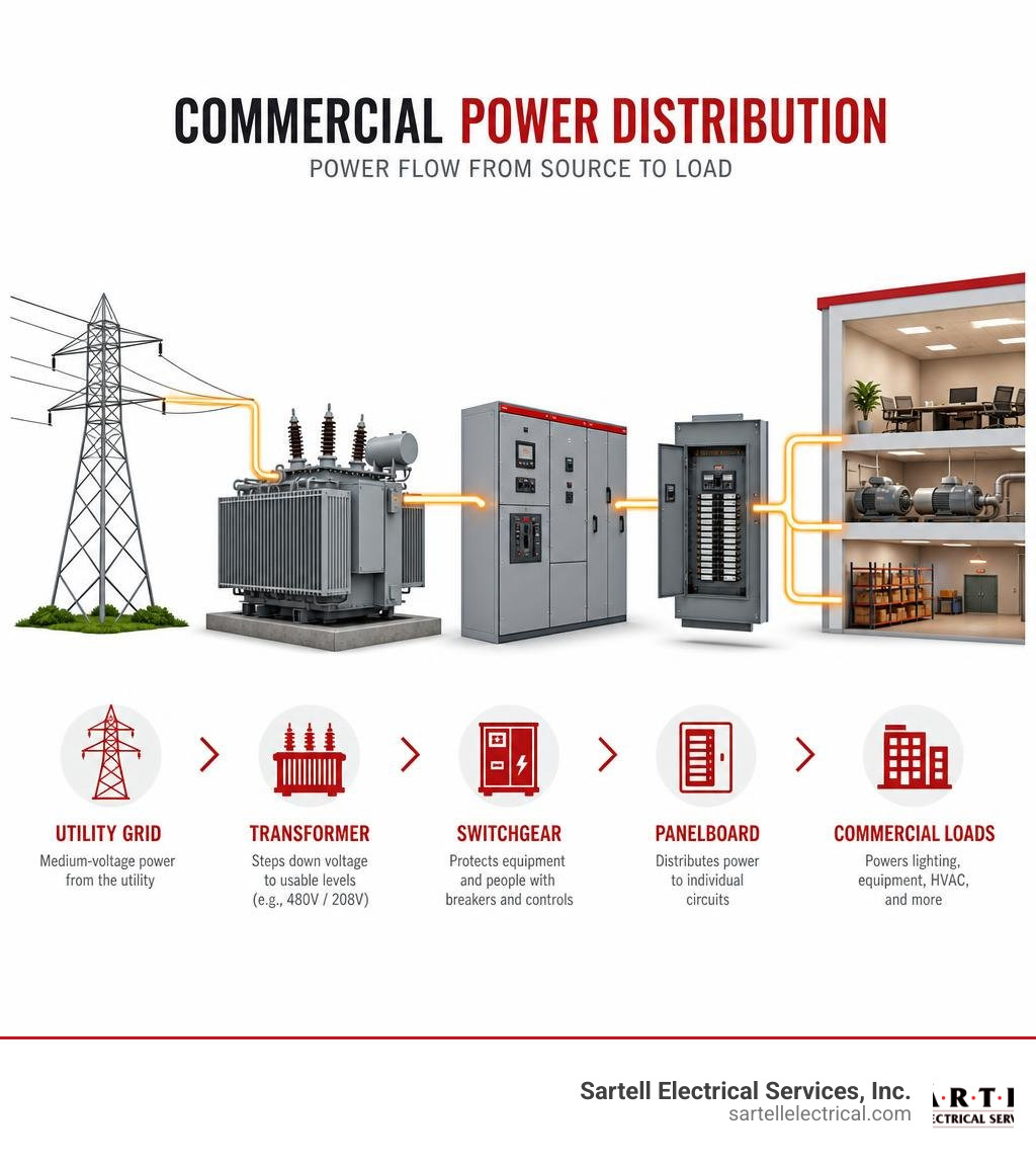
Commercial power distribution is the system that takes incoming utility electricity and safely delivers it — at the right voltage, capacity, and reliability — to every load in your building.
Here's a quick breakdown of what that means in practice:
- Source: Utility grid delivers medium-voltage power (typically 4–35 kV) to your facility
- Step-down: Transformers reduce voltage to usable levels (commonly 480V or 208V)
- Protection: Switchgear and circuit breakers guard equipment and people
- Distribution: Panelboards and busbars route power to individual circuits
- Monitoring: Metering systems track energy use and flag problems
- Backup: Transfer switches and generators maintain power if the grid fails
This is different from plugging a lamp into a wall. Commercial systems handle much higher loads, require three-phase power, and must meet strict safety codes — all while keeping your operations running without interruption.
The stakes are real. In 2013 alone, the U.S. recorded over 3,200 power outages averaging nearly 197 minutes each. For a business, that kind of downtime isn't just inconvenient — it's costly.
I'm Ed Sartell, President of Sartell Electrical Services, Inc., and I've been designing and installing commercial power distribution systems across Massachusetts since 1985. In that time, I've seen how the right distribution design keeps businesses running safely and efficiently — and how the wrong one creates problems that are expensive to fix.
Quick Commercial power distribution definitions:
Understanding Commercial Power Distribution vs. Residential and Industrial Systems
To truly grasp how a commercial power distribution system works, it helps to look at how it compares to residential and heavy industrial environments. While all three systems exist to deliver electrical energy from point A to point B, their scale, complexity, and structural layouts are vastly different.
Residential systems are relatively simple. They typically rely on single-phase power delivered at 120/240 volts. This is more than enough to run your refrigerator, HVAC system, and home entertainment center. The load profile is highly predictable, peaking in the morning and evening when families are home.
Commercial and industrial systems, on the other hand, operate on a completely different level. They utilize three-phase power to deliver continuous, non-pulsing energy. This is essential for driving large electric motors, commercial HVAC chillers, and massive IT infrastructures. However, even commercial and industrial systems have distinct differences in their design goals and operational environments.
| Feature | Residential Systems | Commercial Systems | Industrial Systems |
|---|---|---|---|
| Primary Voltage | 120V / 240V | 120V/208V, 277V/480V | 480V up to 4,160V (and higher) |
| Phase Configuration | Single-phase | Three-phase | Three-phase |
| Load Profile | Low to moderate; morning/evening peaks | High, steady daytime demand; continuous IT loads | Extremely high; highly inductive; 24/7 continuous |
| Typical Infrastructure | Single breaker panel, overhead drop | Switchboards, dry-type transformers, subpanels | Substation transformers, heavy switchgear, bus ducts |
| Key Priority | Basic safety and cost-efficiency | Reliability, flexibility, energy monitoring | Maximum uptime, heavy machinery protection |
In a commercial setting, such as an office building in Boston or a retail complex in Woburn, the primary challenges are load flexibility, power quality, and space optimization. Commercial spaces undergo frequent layout changes (tenant fit-ups), meaning the electrical distribution system must be adaptable.
In contrast, industrial systems are highly specialized and built around heavy machinery, assembly lines, and chemical processing plants. They deal with massive inductive loads that can severely disrupt power quality. If you want to dive deeper into these distinctions, check out our comprehensive guide on Industrial vs Commercial and Everything in Between.
Key Components of a Commercial Power Distribution System
A robust commercial electrical system is only as strong as its individual parts. Each component must be precisely sized, rated, and coordinated to ensure safety and system longevity.

Let’s look at the primary components that make up the backbone of commercial power distribution:
1. Transformers
Since utility lines transmit electricity at medium voltages (often between 4 kV and 35 kV) to minimize transmission line losses, your facility needs a way to step that voltage down to a usable level. This is the job of the transformer. In commercial buildings, we typically install dry-type step-down transformers. These are air-cooled and placed in dedicated electrical rooms to transition utility power down to 480V or 208V.
2. Switchgear and Switchboards
Switchgear and switchboards serve as the central routing stations for your building's electrical system.
- Switchgear is designed to handle high-power applications, offering advanced circuit protection, metal-enclosures, and high short-circuit ride-through capabilities.
- Switchboards are slightly less heavy-duty but serve a similar purpose: they take the main electrical feed and divide it into smaller sections for distribution throughout the building.
For highly demanding applications, modular solutions like the Modular Main Distribution Boards Enclosures provide incredible flexibility, allowing us to customize configurations for air circuit breakers and busbars in space-constrained electrical rooms.
3. Integrated Facility Systems (IFS)
In modern commercial design, saving physical space is a major priority. Traditional designs require mounting separate transformers, switchboards, panelboards, and dry-type transformers along an electrical room wall, which eats up valuable square footage.
To solve this, we often utilize solutions like the Integrated Facility Systems IFS switchboard. These systems consolidate multiple standalone electrical components into a single, factory-assembled unit. By integrating these components, facilities can achieve up to a 50% reduction in total footprint and improve installation times by as much as 80%.
4. Panelboards and Subpanels
Panelboards are the final distribution points before electricity reaches your lights, computers, and wall receptacles. They house the thermal-magnetic circuit breakers that protect individual branch circuits from overcurrents and short circuits.
Primary Voltage Classifications in Commercial Power Distribution
When designing a commercial system, choosing the right voltage configuration is critical for balancing system performance and equipment costs. Commercial buildings in Massachusetts typically utilize one of two primary three-phase configurations:
- 480Y/277V (Three-Phase, Four-Wire): This is the gold standard for mid-to-large commercial properties. The higher 480-volt line-to-line voltage is used to power heavy loads like HVAC compressors, elevators, and large electric pumps. Meanwhile, the 277-volt line-to-neutral connection is ideal for commercial LED lighting systems. Operating at higher voltages reduces the current (amperage) required for the same amount of power, allowing us to use smaller copper wires and conduits, which dramatically lowers installation costs.
- 208Y/120V (Three-Phase, Four-Wire): This configuration is used for standard office environments, retail outlets, and schools. The 120-volt line-to-neutral connection powers standard wall outlets, computers, and office equipment. The 208-volt line-to-line connection runs smaller three-phase motors, commercial kitchen appliances, and small HVAC units.
For a detailed look at how these voltages are mapped out during the engineering phase, refer to the Power Distribution Systems Design Guide for Modern Industries.
Ensuring Reliability and Compliance in Commercial Power Distribution
Operating a commercial facility comes with a heavy burden of regulatory compliance. It isn't just about keeping the lights on; it's about protecting human life and expensive assets from electrical hazards.
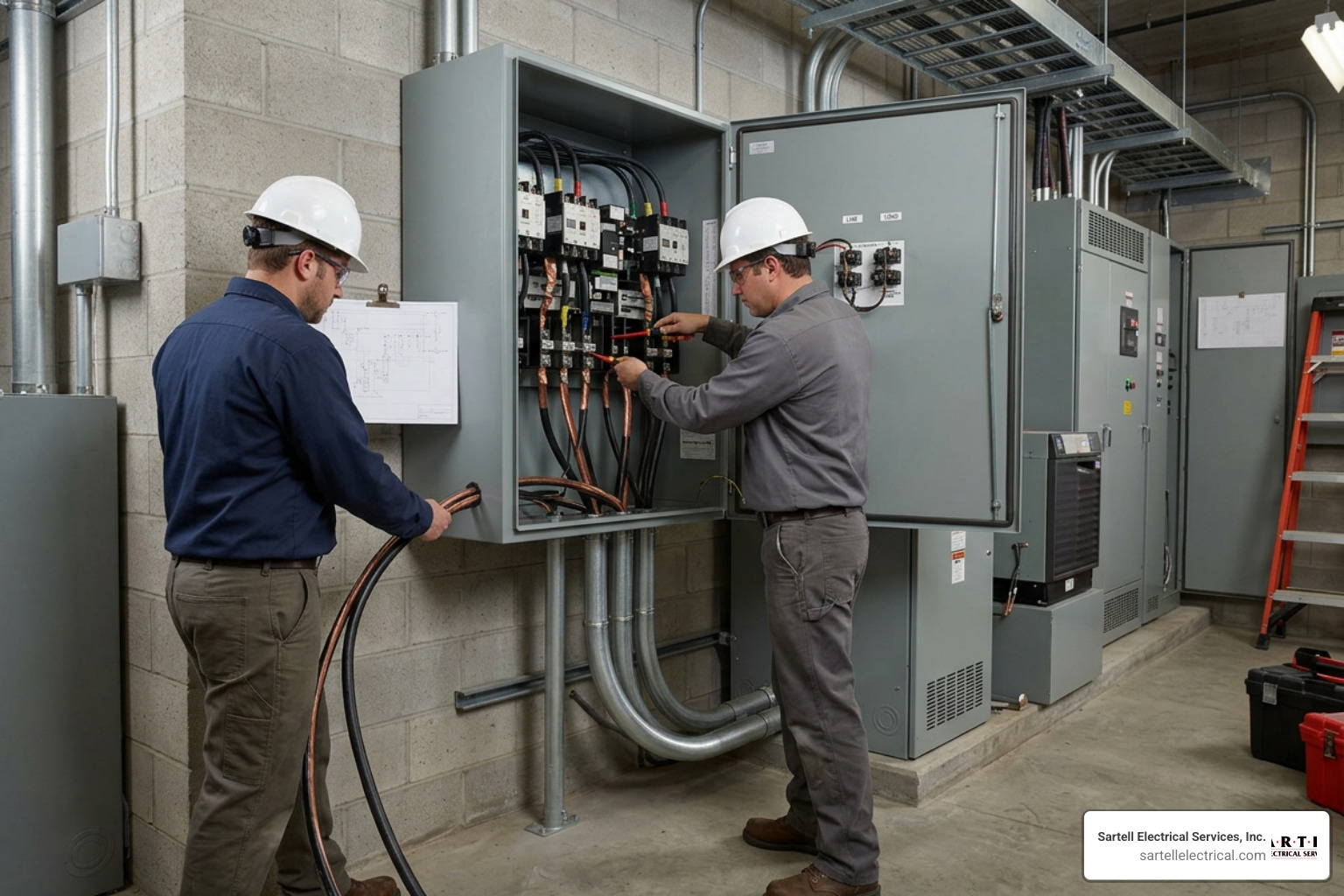
To ensure safety and reliability, commercial power systems must strictly adhere to three primary standards:
1. The National Electrical Code (NEC)
The NEC (NFPA 70) dictates the minimum standards for safe electrical design, installation, and inspection. It covers everything from wire sizing and conduit fill to grounding and overcurrent protection. In Massachusetts, state-specific amendments are periodically integrated, making it essential to work with a local licensed contractor who understands the exact codes enforced in your town, whether you are in Reading, Andover, or Boston.
2. NFPA 70B (Standard for Electrical Equipment Maintenance)
Historically, electrical maintenance was treated as a "best practice." However, NFPA 70B has transitioned into a mandatory standard. It requires commercial facility managers to implement formal, preventive maintenance programs for their electrical distribution equipment. This includes regular infrared thermography (thermal imaging) to spot overheating connections, contact resistance testing, and physical cleaning of switchgear. You can learn how to structure your facility's plan in our Commercial Electrical System Maintenance Guide.
3. OSHA 70E (Standard for Electrical Safety in the Workplace)
OSHA 70E focuses on protecting personnel from the hazards of shock, electrocution, and arc flash incidents. An arc flash is an explosive release of energy caused by an electrical fault. It can reach temperatures hotter than the surface of the sun. OSHA 70E requires facilities to perform arc flash hazard analyses, label electrical equipment with safety boundaries, and ensure that maintenance personnel wear appropriate Personal Protective Equipment (PPE).
Integrating Backup Systems into Commercial Power Distribution
When the utility grid fails, your business cannot afford to grind to a halt. Incorporating emergency backup systems directly into your commercial power architecture is the only way to guarantee business continuity.
The system relies on three critical elements working in perfect harmony:
- Automatic Transfer Switches (ATS): The ATS is the brain of your backup system. It constantly monitors incoming utility power. If the voltage drops or cuts out completely, the ATS commands the backup generator to start. Once the generator reaches the correct speed and voltage, the ATS safely disconnects the building from the utility grid and connects it to the generator. This transition happens in seconds.
- Generator Docking Stations (Tap Boxes): For facilities that do not have a permanent, multi-million-dollar standby generator, a generator docking station is a brilliant, cost-effective alternative. It is a permanently mounted outdoor enclosure that connects directly to your main switchboard. If an extended outage occurs, a portable roll-up generator can be delivered to your site and plugged directly into the docking station using quick-connect Cam-Lok cables, restoring power in minutes without complex field wiring.
- Paralleling Switchgear: In massive commercial spaces, data centers, or healthcare facilities, a single generator might not be enough. Paralleling switchgear allows multiple generators to synchronize their electrical outputs and connect to the same busbar. This provides incredible redundancy — if one generator fails to start, the remaining units can still power your critical loads.
For a deeper dive into designing emergency electrical systems, explore our Commercial Electrical Services Ultimate Guide.
Permanent vs. Portable Power Solutions for Commercial Facilities
As commercial operations evolve, facility managers often find themselves needing to choose between permanent infrastructure and temporary, portable power setups. Each has its place, and a smart facility design often utilizes a hybrid approach.
Permanent power solutions are the standard, hardwired installations that form the core of your building. These include your main switchboards, permanent dry-type transformers, and dedicated branch circuit panelboards. They are designed for long-term reliability, maximum energy efficiency, and compliance with building codes. Permanent systems are ideal for your day-to-day business operations where loads remain relatively stable.
Portable power solutions, on the other hand, offer unmatched flexibility. These include portable transformers, distribution panels, "spider boxes" (compact temporary distribution units), and heavy-duty cable assemblies.
Portable solutions are highly appropriate in several commercial scenarios:
- Renovations and Tenant Fit-Ups: Providing safe, temporary power to construction crews without interrupting operations in other parts of the building.
- Disaster Recovery: Restoring power to critical circuits after severe weather events or equipment failure.
- Outdoor Events & Seasonal Demands: Powering temporary structures, outdoor retail events, or specialized equipment.
Integrating these two approaches requires careful planning. For example, installing a permanent quick-connect docking panel on the exterior of your building allows you to seamlessly plug in portable generator systems whenever the need arises. To learn more about how to wire your facility for both scenarios, take a look at our Commercial Electrical Wiring Insights.
Managing Power Quality, Load Balancing, and Energy Efficiency
In modern commercial facilities, the quality of the power running through your conduits is just as important as the quantity. Poor power quality can ruin sensitive office electronics, cause LED lights to flicker, overheat electric motors, and lead to massive utility penalties.
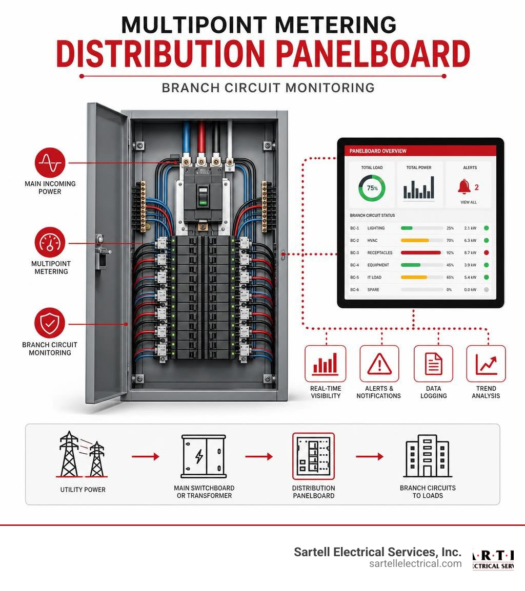
Managing your power system effectively involves focusing on three key areas:
Power Factor Correction
Power factor is a measure of how effectively your system converts electrical energy into useful work. Inductive loads, like large HVAC motors and compressors, draw "reactive power" that does not perform real work but must still be supplied by the utility.
If your power factor drops too low (typically below 90% or 0.90), local utilities like Eversource or National Grid will hit you with expensive power factor penalties on your monthly bill. Installing power factor correction capacitor banks at your main service entrance solves this by supplying the necessary reactive power locally, keeping your utility bills low.
Harmonic Distortion Mitigation
Today's office buildings are packed with non-linear loads, including computers, servers, LED lighting drivers, and variable frequency drives (VFDs). These devices pull current in short, rapid pulses rather than a smooth sine wave. This creates "harmonics" — high-frequency electrical noise that distorts your system.
Left unchecked, harmonics cause neutral wires to overheat, trip circuit breakers unexpectedly, and shorten the lifespan of transformers. We mitigate this by installing active harmonic filters and utilizing line reactors on VFDs.
Smart Metering and Load Balancing
If one phase of your three-phase system is carrying significantly more load than the others, it leads to voltage imbalances, increased energy losses, and overheated equipment.
To prevent this, we utilize advanced systems like the Branch circuit metering panel. These panels feature integrated multipoint meters that track energy usage on a circuit-by-circuit level. This real-time data allows facility managers to balance loads across all three phases, benchmark energy consumption, and identify energy-wasting equipment before it fails.
This level of detailed planning is especially critical for specialized, power-hungry environments. If you are managing a high-density environment, you can read our guide on Data Center Power Planning to see how these principles apply at scale.
Frequently Asked Questions
What are the most common voltage configurations used in commercial buildings?
The two most common configurations are 480Y/277V and 208Y/120V three-phase, four-wire systems. 480Y/277V is preferred for heavy machinery, large HVAC systems, and commercial lighting because it reduces current and allows for smaller wiring. 208Y/120V is standard for general office spaces, convenience outlets, and everyday electronics.
How often should commercial electrical distribution equipment be maintained?
According to NFPA 70B standards, commercial electrical equipment should undergo formal, preventive maintenance at least once a year. This includes infrared thermography to detect loose, hot connections. Physical inspections, cleaning, and mechanical testing of circuit breakers should be performed every one to three years, depending on the operating environment.
What is the difference between switchgear and switchboards?
While both distribute power, switchgear is built for higher-voltage, high-power environments (often up to 38 kV) and features metal-enclosed, draw-out power circuit breakers designed to withstand short circuits for up to 30 cycles. Switchboards are typically used for lower-voltage applications (600V and below), are front-accessible, utilize molded-case circuit breakers, and require a smaller physical footprint.
Conclusion
Designing, installing, and maintaining a commercial power distribution system is a highly complex task that directly impacts your business’s bottom line, safety, and operational continuity. From stepping down utility voltages to managing power quality and ensuring compliance with modern NFPA 70B standards, every decision requires expert engineering and precise execution.
At Sartell Electrical Services, Inc., we have spent over 30 years helping businesses throughout Greater Boston and Eastern Massachusetts navigate these exact challenges. Based in Reading, MA, our team of highly skilled Commercial Electricians is committed to delivering excellence, safety, and unmatched customer service on projects of all sizes.
Whether you are planning a tenant fit-up, upgrading your facility's switchgear, or implementing a mandatory preventive maintenance program, we are here to help. Reach out to us today to discuss your next commercial project and ensure your business stays powered for the future.
Is Professional GFCI Installation in Andover MA Worth It?
Quick answer for Andover homeowners and property managers:
| What you need to know | The short answer |
|---|---|
| What is a GFCI outlet? | A safety device that cuts power within 1/40th of a second when it detects a current imbalance |
| Where are they required in MA? | Kitchens, bathrooms, laundry rooms, garages, outdoor areas, basements, crawlspaces |
| Can I install one myself? | Technically yes, but wiring errors create serious risks — a licensed electrician is strongly recommended |
| How much does it cost in Andover? | Simple repairs start around $150; full installations vary by scope |
| Do I need a permit in Andover? | Yes — a licensed contractor must file an electrical permit within 5 days of starting work |
GFCI installation in Andover MA is one of the most important electrical upgrades you can make to protect your home or commercial property. These small devices react faster than a heartbeat to shut off power when they sense something is wrong — preventing electrical shocks that can seriously injure or kill. Yet many Andover homes, especially older ones, still lack proper GFCI protection in the areas where it matters most.
If your property has outdated outlets, ungrounded two-prong receptacles, or outlets near water that have never been upgraded, you may be out of compliance with Massachusetts electrical code — and more importantly, at real safety risk.
I'm Ed Sartell, President of Sartell Electrical Services, Inc., and I've been overseeing residential and commercial electrical work across Massachusetts since 1985 — including hundreds of GFCI installation projects in Andover MA and the surrounding Merrimack Valley. In this guide, I'll walk you through everything you need to know to make the right decision for your property.
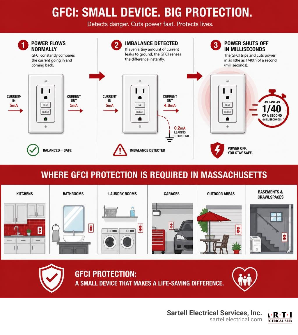
Why Professional GFCI Installation Andover MA is Essential
To understand why professional installation is so critical, we first have to look at what a GFCI actually does. GFCI stands for Ground Fault Circuit Interrupter. In simple terms, it is an ultra-sensitive safety monitor built right into your wall outlet or electrical panel.
Under normal operating conditions, the electricity flowing into an appliance through the "hot" wire should exactly match the current returning through the "neutral" wire. But if electricity finds an alternative path to the ground—such as through water, a damp floor, or worse, your body—a "ground fault" occurs.
A GFCI outlet continuously monitors this electrical balance. If it detects a differential current as tiny as 4 to 6 milliamperes, it assumes something is terribly wrong. According to OSHA standards, a GFCI reacts in approximately 1/40th of a second to completely stop the flow of electricity. This lightning-fast response prevents the current from passing through your heart, effectively saving you from a lethal electrical shock.

Without these devices, a standard outlet will keep pushing electricity through a fault until the main circuit breaker trips. Unfortunately, standard breakers are designed to protect your home's wiring from overheating and catching fire; they will not trip at the low current levels that can stop a human heart. This is why having properly functioning GFCI protection is non-negotiable for residential safety. To learn more about how these devices fit into your overall home safety plan, check out our guide on Electrical Safety Checks and see how local home inspectors evaluate these systems at GFCI Receptacles - Massachusetts Home Inspections.
Where Massachusetts Code Mandates GFCI Installation Andover MA
In Massachusetts, electrical safety is governed by the Massachusetts Electrical Code (MEC), which adopts the National Electrical Code (NEC) alongside state-specific amendments. The state transitioned to the updated NEC standards, which significantly expanded where ground-fault protection must be installed.
Generally speaking, any area of your home where water and electricity could potentially shake hands must have GFCI protection. According to Massachusetts regulations, these locations include:
- Bathrooms: All receptacles must be GFCI-protected, without exception.
- Kitchens: All receptacles serving countertop surfaces, plus any outlet within 6 feet of the kitchen sink.
- Laundry Areas: Any outlet located within 6 feet of a sink, washing machine, or laundry tub.
- Garages and Accessory Buildings: Any unfinished space or work area where damp concrete floors can create an easy path to ground.
- Basements and Crawlspaces: Both finished and unfinished basements require complete GFCI protection.
- Outdoor Spaces: All exterior outlets must be GFCI-protected and housed in weatherproof, "while-in-use" covers.
If you are planning renovations or simply want to ensure your home meets local guidelines, you can review the official state requirements on the AFCI and GFCI Requirements in Massachusetts | Massachusetts Electrical Authority page.
GFCI vs. AFCI: Two Essential Safety Technologies
We often hear homeowners ask, "If I have GFCI outlets, do I still need AFCI protection?" The short answer is yes. They are two entirely different safety systems designed to protect against two entirely different hazards.
While a GFCI protects people from getting shocked, an AFCI (Arc-Fault Circuit Interrupter) protects your property from catching fire. AFCIs detect dangerous electrical arcing—sparking that occurs when wires are damaged, loose, or pierced by a stray nail behind your walls.
| Feature | GFCI (Ground Fault Circuit Interrupter) | AFCI (Arc-Fault Circuit Interrupter) |
|---|---|---|
| Primary Purpose | Prevents electrical shock and electrocution | Prevents electrical fires caused by arcing wires |
| How It Works | Detects current imbalances between hot and neutral wires | Detects abnormal sparking/arcing patterns in wiring |
| Reaction Speed | Approx. 1/40th of a second | Instantaneous upon detecting signature arc patterns |
| Typical Locations | Kitchens, bathrooms, garages, outdoors, basements | Bedrooms, living rooms, dining rooms, hallways |
| Required by Code | Yes, near water sources and damp environments | Yes, throughout standard living spaces |
Both technologies work together to form a complete safety shield for your household. To dive deeper into how these systems protect your home from hidden electrical dangers, read our comprehensive resource, Don't Get Zapped: A Guide to Home Electrical Safety Checks.
Why Upgrading Older Andover Homes is Crucial
Andover is famous for its beautiful, historic neighborhoods. From classic Colonials near downtown to historic Victorians near the Academy, our town’s architecture is unmatched. However, historic charm often comes with historic electrical systems.
Many older homes in Andover still feature original two-prong outlets. These outlets are ungrounded, meaning they lack the third "ground" wire that provides a safe pathway for stray electricity to escape. Running modern appliances, computers, and home entertainment systems on ungrounded circuits is a recipe for damaged electronics and increased fire risks.

Updating these systems is a vital part of property preservation. If you want to understand how ground faults behave in older wiring systems, take a look at our step-by-step article on Fixing Ground Faults in Your Home Electrical System.
Upgrading Two-Prong Outlets to GFCI Receptacles
Rewiring an entire historic home to add a ground wire to every single outlet can be a massive, invasive, and expensive undertaking. Fortunately, the National Electrical Code offers an approved, cost-effective alternative for older properties: retrofitting with GFCI outlets.
Under NEC rules, you can replace an ungrounded two-prong outlet with a three-prong GFCI outlet. Even though there is no physical ground wire attached to the GFCI, the internal circuitry of the device will still trip and protect you if a ground fault occurs.
However, there is a strict catch: these retrofitted outlets must be clearly labeled with stickers that read "No Equipment Ground" and "GFCI Protected." This alerts future users that while they are safe from shocks, sensitive electronic equipment (like high-end gaming PCs or surge protectors) won't have a true ground path to drain away excess voltage. If you want to see exactly how these units are wired under different configurations, you can watch this helpful How to Install a GFCI Outlet with 2 or 4 Wires, Step-by-Step Guide.
Warning Signs Your Outlets Need Immediate GFCI Installation Andover MA
Like any mechanical or electronic device, GFCI outlets do not last forever. Most modern GFCI receptacles have a lifespan of about 10 to 15 years. If your outlets are displaying any of the following warning signs, they need to be evaluated and replaced immediately:
- Warm or Discolored Faceplates: If an outlet cover feels warm to the touch or shows signs of yellowing, browning, or melting, it indicates excessive heat buildup from loose internal connections. This is a severe fire hazard.
- Physical Cracks or Loose Plugs: Cracked plastic housings allow dust and moisture to enter the device. If your plugs slip out of the outlet easily, the internal metal contacts are worn out and can cause dangerous arcing.
- Failure to Reset: When you press the "Test" button, the "Reset" button should pop out and cut power. If the button refuses to click back in, or if the outlet remains dead even after pressing reset, the internal sensor has failed.
- Persistent Tripping: If an outlet trips constantly without a heavy appliance plugged into it, you may have an active ground fault hidden in the walls, or the GFCI mechanism itself has degraded.
If you are dealing with an outlet that refuses to cooperate, read our diagnostic guide on GFCI Not Resetting to determine if it's a simple fix or if it's time to call in the professionals.
The Professional Installation Process and Local Regulations
When it comes to municipal rules, the Town of Andover takes electrical safety seriously. According to the Andover Building Division, any electrical work beyond minor maintenance requires an electrical permit.
By local law, this permit must be filed by a licensed electrical contractor within 5 days of starting the work. Once the project is complete, the local wire inspector must examine the installation to verify that it complies with all state and local codes. Doing electrical work without a permit can lead to fines, voided home insurance policies, and issues when you try to sell your home. You can review the official municipal requirements directly on the Andover Building Permit Checklist or contact a qualified Andover MA Electrician to handle the paperwork for you.
Why DIY GFCI Installation is a Safety Risk
With hundreds of online DIY tutorials available, it can be tempting to try installing a GFCI outlet yourself. However, electrical work is unforgiving. A single misplaced wire can turn a safety device into a serious hazard.
The most common mistake DIYers make is confusing the "Line" and "Load" terminals on the back of the GFCI receptacle.
- The Line terminals are for the incoming power from your electrical panel.
- The Load terminals are designed to send protected power downstream to other outlets on the same circuit.
If you wire these backward, the outlet itself will still supply power, but the safety trip mechanism will be completely bypassed. You’ll have an outlet that looks like a GFCI, resets like a GFCI, but will not protect you during a ground fault. Other common errors include reverse polarity, loose wire nuts that cause electrical fires, and failing to properly ground the metal junction box. If you suspect your current outlets have been wired incorrectly, read our guide on How to Fix a Ground Fault in 5 Simple Steps to understand how we identify and correct these wiring faults safely.
What to Expect: Installation Timeline and Cost in Andover, MA
When you hire a professional team like Sartell Electrical Services, Inc., the installation process is smooth, efficient, and transparent.
For a standard home, replacing a few outdated outlets with new GFCI receptacles typically takes between 1 to 2 hours. If we need to install a dedicated circuit or run new wiring from your main electrical panel, the job may take a half or full day.
In terms of cost, simple repairs and single-outlet swaps generally start around $150. The total investment will depend on:
- The number of outlets being replaced or added.
- Whether your existing electrical boxes are large enough to house modern, bulky GFCI units.
- The cost of the local Andover electrical permit.
- Whether your panel requires a specialized GFCI circuit breaker rather than individual wall outlets.
We believe in providing upfront, clear pricing before any work begins so you are never surprised by the final bill. You can learn more about how we structure our residential projects by visiting our Residential Electrical Services Complete Guide.
Frequently Asked Questions About GFCI Outlets
How often should I test my GFCI outlets?
You should test all the GFCI outlets in your home once a month. To do this, simply plug a small lamp or outlet tester into the receptacle, then press the "Test" button. The lamp should turn off instantly, and the "Reset" button should pop out. Press "Reset" to restore power. If the light stays on or the button fails to pop, the device is faulty and must be replaced. If you suspect an issue with your home's grounding system during these tests, consult our Ground Fault Repair guide for troubleshooting tips.
Can a GFCI outlet protect downstream outlets on the same circuit?
Yes! By utilizing the "Load" terminals on the back of a GFCI receptacle, a single GFCI outlet can extend ground-fault protection to multiple standard "downstream" outlets connected on the same circuit. This is a highly efficient way to bring entire rooms up to code without buying expensive GFCI units for every single wall opening. To learn more about circuit design and downstream protection, check out our Residential Electrical Services Complete Guide.
What should I do if my GFCI outlet keeps tripping?
If a GFCI outlet trips repeatedly, it is doing its job. It usually means one of three things: a "leak" of electrical current is occurring (often caused by a faulty appliance like a damp outdoor light or a failing toaster), the circuit is overloaded with too many high-draw devices, or the GFCI unit itself has worn out and needs replacement. Do not ignore a constantly tripping outlet. For a detailed walkthrough on how to isolate the problem, read Stop the Trip: A Guide to Fixing Your GFCI Outlet.
Conclusion
At the end of the day, GFCI installation in Andover MA is not just about checking a box for your local building inspector or passing a home sale contingency. It is about protecting your family, your tenants, and your property from entirely preventable electrical accidents.
Since 1985, our team at Sartell Electrical Services, Inc. has built a reputation across the North Shore and Merrimack Valley for safety, reliability, and exceptional customer care. Whether you need a single bathroom outlet upgraded or want a comprehensive safety audit of your historic Andover home, we are here to help.
Don't wait for a warning shock to tell you your outlets are outdated. If you're ready to secure your property or need help troubleshooting an annoying electrical issue, read our expert resource on how to Stop the Trip: A Guide to Fixing Your GFCI Outlet or reach out to us today to schedule your professional installation!
How Power Actually Gets From the Grid to Your Front Door
Power distribution systems are the final link in the electricity delivery chain — moving power from high-voltage transmission lines down to a usable voltage at your home or business.
Here is a quick overview of how the process works:
- Generation — A power plant produces electricity at medium voltage.
- Step-up transmission — Transformers boost voltage to 44 kV–765 kV for efficient long-distance travel.
- Distribution substation — Voltage is stepped down to 2 kV–35 kV for local delivery.
- Primary distribution lines — Medium-voltage feeders carry power through your neighborhood.
- Pole or pad-mounted transformer — Voltage drops again to 120/240 V for residential use.
- Service drop — The final connection runs from the utility pole directly to your meter.
The system sounds simple. But behind every light switch is a remarkably complex web of substations, transformers, feeders, protective devices, and miles of wire — all engineered to keep power flowing safely and reliably, around the clock.
Distribution is not a small part of the picture, either. It accounts for roughly 32% of the total cost of electricity paid by U.S. consumers. And with 3,236 reported power outages recorded in 2013 alone — averaging 197 minutes each — how that infrastructure is designed and maintained matters enormously for businesses and homeowners alike.
I'm Ed Sartell, President of Sartell Electrical Services, and I've been working with power distribution systems at the commercial and residential level across Massachusetts since 1985. In this guide, I'll walk you through exactly how the grid works — from the substation to your service panel — so you can make smarter, more informed decisions about your electrical infrastructure.
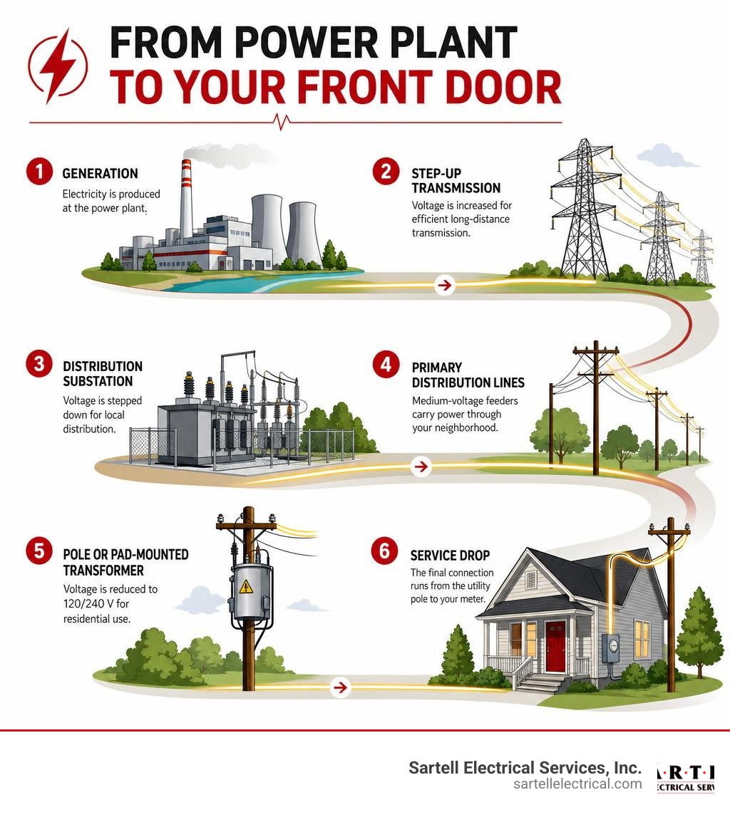
Related content about Power distribution systems:
The Anatomy of Modern Power Distribution Systems

At its core, a power distribution system is designed to take bulk electrical energy from the high-voltage transmission network and safely deliver it to end-use equipment. Whether we are looking at a municipal utility in Middlesex County or a large industrial complex in Boston, MA, the fundamental anatomy of these systems remains remarkably consistent.
The system begins at the distribution substation. This critical facility houses the heavy machinery required to transition electricity from transmission-level voltages down to distribution levels. Within the substation, you will find busbars, power transformers, switchgear, and monitoring instruments that work in unison to control the flow of electricity.
From the substation, a network of primary feeders extends outward. These feeders can be overhead lines mounted on utility poles or underground cables buried beneath city streets. Feeders act as the primary highways of local power delivery, carrying medium-voltage power closer to residential neighborhoods, commercial districts, and industrial parks. Along these pathways, protective devices such as fuses, circuit breakers, and reclosers are strategically installed to isolate faults and prevent widespread blackouts.
For engineers and facility managers planning these layouts, the Electrical Distribution Fundamentals Design Guide Data Bulletin serves as an essential reference, detailing the standard physical and electrical parameters required to build a code-compliant, highly functional system.
Primary vs. Secondary Power Distribution Systems
To understand the modern grid, we must distinguish between the primary and secondary distribution systems.
The primary distribution system operates at medium voltage levels, typically ranging from 2 kV up to 35 kV phase-to-phase. This system is responsible for moving power over moderate distances from the substation to the immediate vicinity of the customer. In our service areas across Greater Boston, primary feeders usually run at 4 kV, 13.8 kV, or 34.5 kV. Large industrial facilities often purchase power directly at these primary medium voltages because they operate heavy machinery and maintain their own private substations.
The secondary distribution system operates at low voltage levels, delivering power directly to the customer’s electrical panel. For residential homes, this is typically the familiar 120/240V single-phase service. For commercial and light industrial buildings, we frequently design and service 208Y/120V or 488Y/277V three-phase systems.
To dive deeper into how these different voltage levels are utilized in commercial environments, you can read our comprehensive Power Distribution Systems Design Guide for Modern Industries.
The Role of Transformers in Power Distribution Systems
Without the humble transformer, modern electricity delivery would be economically impossible. Transformers utilize electromagnetic induction to change AC voltage levels with minimal energy loss. In power distribution systems, their primary job is the step-down function: reducing dangerous, medium-voltage primary power to safe, usable low-voltage secondary power.
However, operating these massive electromagnetic devices introduces unique physical challenges:
- Magnetizing Current: When a transformer is energized, it requires a small continuous current to maintain the magnetic field in its steel core.
- Inrush Currents: When a transformer is first switched on, it can draw a momentary surge of current up to 10 to 15 times its rated full-load current. This transient inrush must be carefully accounted for so it does not trip protective relays.
- Connection Groups (Vector Groups): Transformers are configured in specific winding arrangements, such as Delta-Wye ($Delta$-Y) or Wye-Wye (Y-Y). The choice of connection group determines phase displacement, grounding capabilities, and how harmonic currents are managed.
For those interested in the deep engineering mathematics behind transformer impedance, voltage drop formulas, and connection configurations, the Distribution Automation Handbook provides exhaustive technical documentation.
Network Topologies: Radial, Loop, and Meshed Configurations
The physical layout, or topology, of a distribution network directly dictates its cost, complexity, and reliability. Depending on whether we are servicing a suburban neighborhood in Andover or a high-density data center in Boston, different configurations are utilized.
| Topology Type | Initial Cost | Reliability Level | Redundancy | Typical Application |
|---|---|---|---|---|
| Radial | Low | Low to Moderate | None | Rural areas, residential suburbs |
| Loop (Ring) | Moderate | High | Single-fault tolerance | Commercial districts, schools |
| Meshed (Network) | Very High | Extremely High | Multi-fault tolerance | Downtown urban cores, critical facilities |
- Radial Feeders: This is the simplest and least expensive layout, structured like a tree. Power flows from a single source outward to the customers. If a tree branch falls on a radial line, everyone downstream of the fault loses power.
- Loop-Type Feeders: In a loop configuration, the feeder makes a complete circle, starting and ending at the substation (or connecting two separate substations). If a fault occurs, switches can isolate the damaged section while power is routed to the remaining customers from the opposite direction.
- Meshed Networks: The gold standard of reliability. In a meshed system, multiple primary and secondary lines are interconnected in a grid-like pattern, supplied by multiple transformers in parallel. If one or even two sources fail, power instantly flows through alternative paths without a single second of interruption.
Regional Voltage Variations and Historical Evolution
Have you ever wondered why North America uses a 120/240V split-phase system while Europe and most of the world use a 220-240V single-phase standard? The answer lies in the famous "War of the Currents" during the late 19th century.
Thomas Edison pioneered the first commercial direct current (DC) distribution system, launching the Pearl Street Station in lower Manhattan in 1882. Edison's system delivered low-voltage DC directly to customers. Because low-voltage DC could not travel more than a mile without massive voltage drop, it required frequent, small generating stations.
Nikola Tesla and George Westinghouse countered with alternating current (AC). By using transformers, AC power could be stepped up to extremely high voltages, transmitted over hundreds of miles with minimal loss, and then stepped down near the customer. AC quickly won the war because of these massive economies of scale.
In the United States, early incandescent light bulbs were designed to run on 110V to 120V for safety and filament durability. When the grid expanded, the U.S. chose to keep the 120V standard for safety, using a split-phase 120/240V transformer configuration to allow larger appliances (like dryers and ovens) to run on 240V.
Conversely, European countries built their grids later. They opted to double the primary residential voltage to 220-240V. This allowed them to deliver twice as much power over the same thickness of copper wire, saving immense infrastructure costs, albeit at a slightly higher safety risk.
Protecting the Grid: Circuit Breakers, Fuses, and Relays

When an electrical fault occurs — such as a tree branch shorting out two phases or a car hitting a utility pole — the resulting short-circuit current can be thousands of times higher than normal. Without rapid protection, equipment would literally melt, and fires would break out.
Modern protection schemes rely on a coordinated hierarchy of devices:
- Circuit Breakers: Large, automatic switches capable of safely interrupting massive short-circuit currents. High-quality modular hardware, such as the System pro E power (ABB Enclosures) or the SIVACON S8 power distribution boards | Siemens, are designed to house these critical breakers safely in commercial and industrial settings.
- Fuses: The simplest protection device. A small metal wire designed to melt and open the circuit when current exceeds a specific threshold. Fuses are highly reliable but must be manually replaced after they blow.
- Reclosers: Because roughly 80% of overhead distribution faults are temporary (like a passing branch brushing against a wire), reclosers act as smart circuit breakers. They open when a fault is detected, wait a few seconds for the fault to clear, and then automatically "reclose" to restore power.
- Sectionalizers: These are smart switches installed downstream of a recloser. They do not interrupt fault currents themselves; instead, they count the number of times the upstream recloser opens. If the fault persists after a set number of attempts, the sectionalizer opens during the "dead time" to isolate the damaged line, allowing the recloser to restore power to the rest of the loop.
- Protective Relays: The "brains" of the protection system. They monitor current, voltage, and frequency, sending trip signals to circuit breakers when anomalies are detected.
To understand how to maintain these protection devices and ensure they operate correctly during a fault, check out our Industrial Electrical Maintenance Complete Guide.
Substation Insulation Coordination and Overvoltage Protection
Primary distribution substations are highly vulnerable to overvoltages caused by lightning strikes, grid switching operations, and temporary system faults. To protect millions of dollars of equipment, engineers practice insulation coordination.
This process involves matching the dielectric strength (insulation level) of substation equipment with the expected overvoltages in the system. The primary line of defense is the surge arrester. Modern substations utilize zinc oxide (ZnO) surge arresters. Under normal voltages, these devices act as insulators. However, when a high-voltage lightning surge hits, the zinc oxide instantly becomes highly conductive, safely diverting the massive current to the ground grid before it can damage the substation transformers.
Voltage Regulation, Power Quality, and Modern Grid Challenges
As electricity travels down miles of distribution lines, it encounters natural resistance and reactance, leading to a phenomenon known as voltage drop. If the voltage drops too low, home appliances can malfunction and industrial motors can overheat.
Utilities are legally required to keep customer voltage within a tight range (typically $pm 5%$ of nominal voltage). To achieve this, we employ several voltage regulation technologies:
- On-Load Tap Changers (OLTC): Specialized mechanisms built into substation transformers that adjust the turn ratio of the windings on the fly, boosting or lowering voltage as demand changes.
- Line Voltage Regulators: Autotransformers installed along long rural feeders that automatically boost voltage back to nominal levels.
- Capacitor Banks: Installed on utility poles or within industrial facilities to provide reactive power support. By counteracting inductive loads (like motors and air conditioners), capacitors improve the overall power factor, reduce line losses, and raise local voltage.
Maintaining high power quality is critical for modern commercial operations. Sensitive electronics cannot tolerate voltage sags, swells, or harmonic distortions. Ensuring your facility has a robust, clean power supply starts with understanding your Critical Electrical System.
Urban, Suburban, and Rural Distribution Dynamics
The physical construction of a distribution system varies wildly depending on the local population density:
- Urban Areas: Characterized by extremely high load density. Because space is limited, urban distribution is almost entirely underground. While undergrounding protects cables from weather and falling trees, it is incredibly expensive, costing five to ten times more than building overhead lines.
- Suburban Areas: Typically a hybrid mix. Primary feeders are often overhead, while newer residential developments utilize underground secondary cables fed from green, pad-mounted transformers in front yards.
- Rural Areas: Characterized by low load density and vast distances. To keep costs down, rural systems rely almost exclusively on overhead lines. In extremely remote areas, utilities may even use Single-Wire Earth Return (SWER) systems, which use a single phase conductor and utilize the earth itself as the return path to minimize pole and wire costs.
Distributed Generation and Smart Grid Integration
The traditional "one-way street" grid model — where power flows exclusively from massive power plants down to consumers — is rapidly changing. Today, we are seeing the rise of distributed generation, with more than 90% of all distributed generation in the U.S. coming from solar power.
While clean energy is fantastic, integrating hundreds of solar arrays into local distribution networks introduces major technical challenges. On sunny afternoons, excess solar generation can cause power to flow backward through the system, creating voltage spikes that can damage household appliances.
To manage this, states like Massachusetts have adopted formal net metering policies, allowing customers to receive credit for the power they feed back into the grid. Additionally, many modern facilities are turning to microgrids — self-contained power systems with local generation and energy storage that can disconnect from the main utility grid and run independently during an outage.
If you are planning a high-reliability facility, such as a server farm or a hospital, integrating these technologies requires careful planning. Learn more about how we handle these complex power requirements in our guide to Data Center Power Planning.
Economics, Regulation, and Reliability of Grid Infrastructure
Maintaining and upgrading our nation's power grid is an astronomical financial undertaking. Since 2000, the utility industry has invested over $275 billion (in 2012 USD) on distribution networks alone. Looking forward through 2030, projected investments to modernize the distribution grid are expected to reach as high as $582 billion.
These investments are heavily regulated. In Massachusetts, the Department of Public Utilities (DPU) acts as the public utility commission, regulating the rates that investor-owned utilities can charge consumers. They must balance the utility's need to recover infrastructure costs with the public's right to affordable, reliable electricity.
Reliability is measured using standardized industry metrics:
- SAIDI (System Average Interruption Duration Index): The average total outage duration experienced by a customer in a year.
- SAIFI (System Average Interruption Frequency Index): The average number of times a customer experiences a sustained outage in a year.
In competitive retail markets, consumers can choose who supplies their electricity, though the local utility still owns, maintains, and charges for the physical distribution lines.
Frequently Asked Questions about Grid Operations
What is the difference between transmission and distribution lines?
Transmission lines are the high-voltage "highways" of the grid (typically 44 kV to 765 kV) designed to move bulk electricity over long distances from remote power plants. They are supported by massive steel towers. Distribution lines are the low-voltage "local streets" (under 50 kV) that deliver power directly to homes and businesses, supported by standard wooden utility poles or buried underground.
Why is alternating current (AC) used instead of direct current (DC) for distribution?
AC is used because it can be easily and efficiently stepped up or down using simple, highly reliable transformers. This allows power to be transmitted at high voltages over long distances to minimize energy losses, and then safely reduced to 120/240V for residential use. While high-voltage DC is used for specific long-distance transmission lines, AC remains the global standard for local distribution.
Why are power lines not always buried underground?
While burying power lines underground protects them from storms, wind, and falling trees, it is extraordinarily expensive. Converting overhead lines to underground cables can cost five to ten times more than building overhead lines. Additionally, underground cables are harder to access for repairs, meaning that while they fail less often, their outages often last much longer when they do occur.
Conclusion
The modern electrical grid is a marvel of engineering, quietly performing a complex balancing act every second of the day. As we move further into 2026, the transition toward renewable energy, smart grid technologies, and electric vehicles means our power distribution systems must become more dynamic, resilient, and intelligent than ever before.
For businesses and industrial facilities across Massachusetts, keeping these systems running efficiently requires expert design, regular maintenance, and a trusted electrical partner. Whether you need a complete switchboard installation, commercial retrofitting, or emergency electrical services, we are here to help.
Contact us today at Sartell Electrical Services to discuss how we can future-proof your facility's electrical infrastructure.
Why Circuit Breaker Repair Is Critical for Business Continuity
Circuit breaker repair is one of the most important — and most overlooked — maintenance priorities for commercial and industrial facilities. A single failed breaker can shut down production lines, compromise critical systems, and create serious fire hazards.
Here is a quick summary of what businesses need to know:
| Question | Quick Answer |
|---|---|
| What causes breaker failure? | Age, overloads, short circuits, power surges, and corrosion |
| How do I know a breaker needs repair? | Frequent tripping, buzzing, hot panel, burning smell, or physical damage |
| Repair or replace? | Repair/refurbish when possible — it costs 40-70% less than replacement |
| Can I do it myself? | No — always use a licensed electrician for safety and code compliance |
| How long does professional repair take? | Typically 2-3 business days; emergency service is often available |
The stakes are high. Faulty circuit breakers are linked to approximately 25% of all residential electrical fires each year. For businesses, the consequences extend beyond fire risk — unplanned downtime, damaged equipment, and liability exposure can all follow a neglected breaker problem.
I'm Ed Sartell, President of Sartell Electrical Services, Inc., and I've been diagnosing and overseeing circuit breaker repair work across Massachusetts since 1985. In this guide, I'll walk you through exactly how to identify, test, repair, and maintain your circuit breakers — so your facility stays safe, compliant, and running.
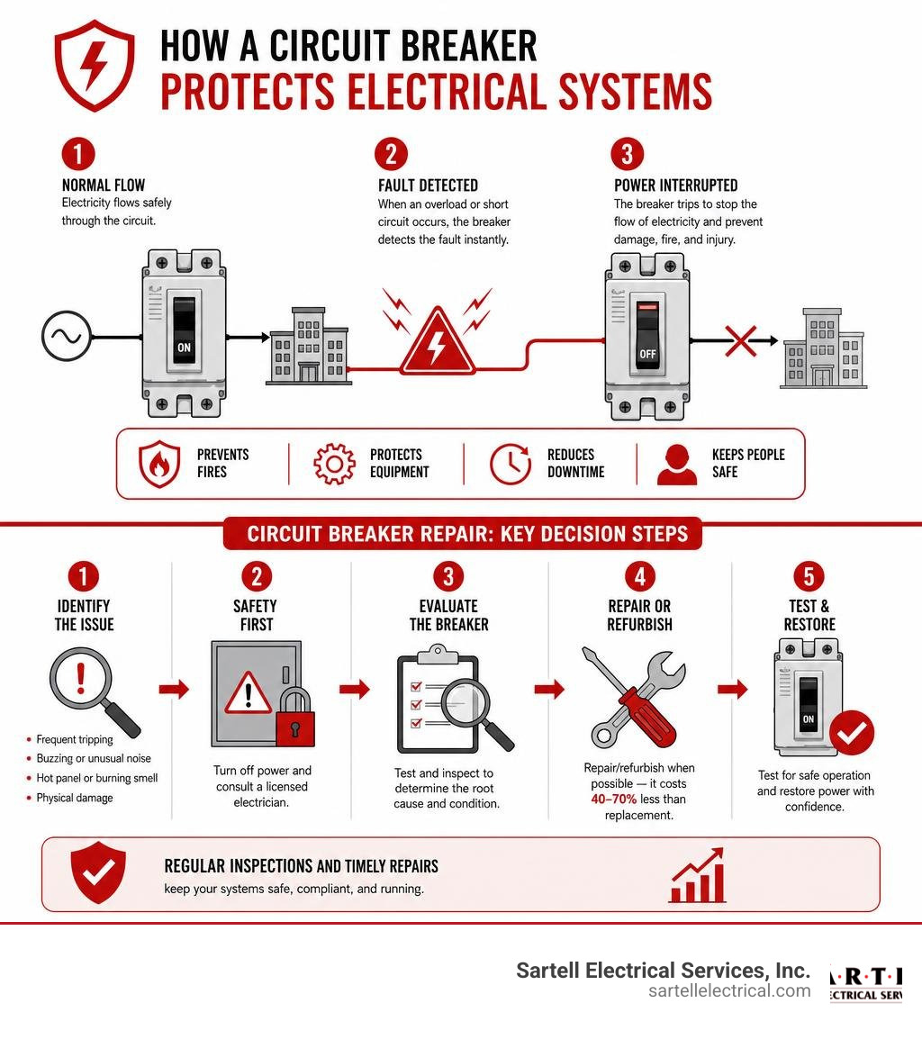
Learn more about Circuit breaker repair:
Understanding Circuit Breaker Failure: Causes and Safety Risks
To keep your facility running smoothly, it helps to understand why these vital safety devices fail in the first place. Circuit breakers are mechanical switches designed to interrupt the flow of electricity when they detect an unsafe surge or fault. However, because they are mechanical devices under constant electrical and physical stress, they do not last forever.
Over time, several factors contribute to the degradation of a circuit breaker:
- Age and Heat Cycling: Every time a breaker handles fluctuating electrical loads, its internal components expand and contract. This constant "heat cycling" weakens internal springs and bi-metallic strips over decades of use.
- Excessive Use: Breakers are safety valves, not light switches. Repeatedly turning circuits on and off using the breaker handle can wear out the mechanical linkages.
- Power Surges: Lightning strikes, utility grid fluctuations, and heavy industrial machinery startups can send massive surges through the breaker, pitting the electrical contacts or melting internal components.
- Environmental Factors: Massachusetts is famous for its humid summers and freezing winters. This moisture, combined with salt air in coastal areas like Boston, Essex County, and Norfolk County, leads to rapid corrosion of the copper and silver contacts inside the panel.
To better understand how these breakers fit into your building's overall electrical framework, you can Learn more about what is a breaker box.
Common Causes of Breaker Malfunctions
When we are called out to perform circuit breaker repair, we usually find that the breaker failed while trying to protect the system from one of three major system faults:
- Overloaded Circuits: This happens when you plug in too many high-draw devices or run heavy machinery beyond the circuit's rated amperage. The breaker heats up and trips to prevent the wires from melting.
- Short Circuits: A short circuit occurs when a hot wire touches a neutral wire. This creates an immediate, massive spike in current that forces the breaker to trip instantly.
- Ground Faults: Similar to a short circuit, a ground fault occurs when a hot wire comes into contact with a grounded portion of the junction box, appliance frame, or ground wire. This is especially dangerous in wet environments.
If your facility is experiencing frequent interruptions, you can check out our detailed guide on the subject: Read our guide on circuit breaker tripping.
The Critical Safety Risks of Neglecting Repairs
Ignoring a faulty breaker is a recipe for disaster. When a circuit breaker fails to trip during an overload or short circuit, the electrical current continues to flow unchecked. The copper wires inside your walls or conduit will rapidly heat up, melt their protective plastic insulation, and ignite surrounding materials.
This is why circuit breaker failures are responsible for roughly 25% of all residential electrical fires each year, and they present an even greater threat in industrial settings.
Beyond structural fires, a malfunctioning breaker can cause:
- Arc Flash Incidents: A catastrophic discharge of electrical energy that can cause severe burns, blindness, and structural destruction.
- Severe Equipment Damage: Sensitive electronics, servers, and industrial motors can be fried instantly if a breaker fails to clear a fault.
- Ground Fault Hazards: Without a functioning breaker to cut power, a ground fault can leave metal machinery casings energized, posing a fatal shock hazard to your employees.
For specialized information on handling ground-level faults, you can Find out about ground fault repair.
How to Diagnose and Test a Malfunctioning Breaker
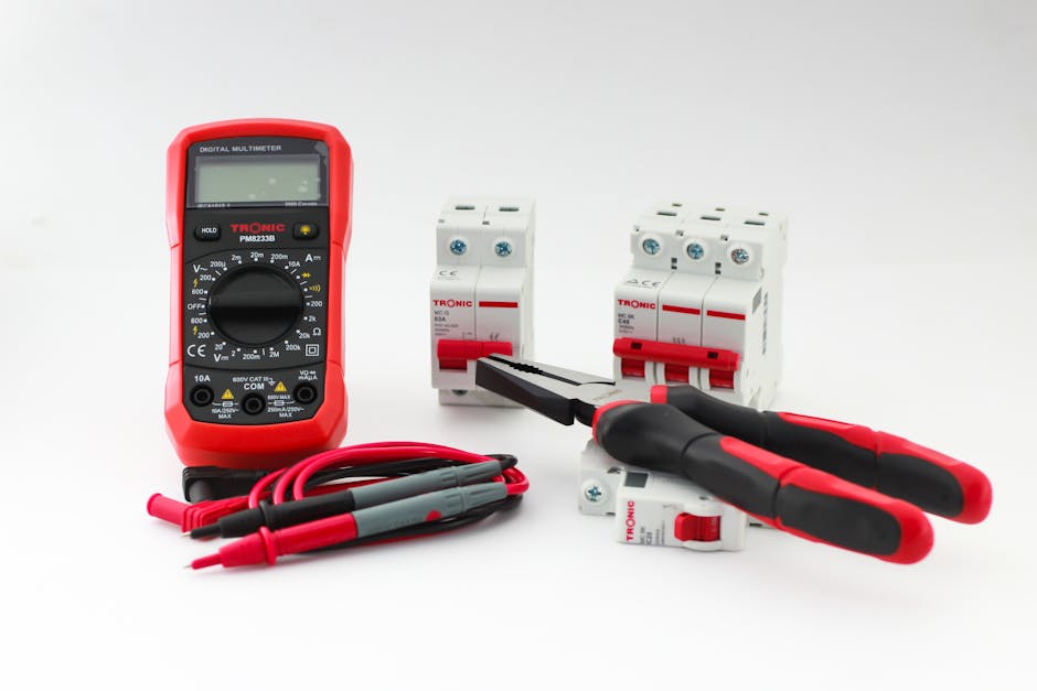
Before jumping into a repair or replacement, a professional technician must perform a series of sophisticated diagnostic tests to pinpoint the exact failure point. You cannot simply look at a breaker and know if its internal mechanisms are functional.
Professional diagnostics typically involve:
- Visual and Mechanical Inspection: Checking for physical cracks, discoloration from heat, loose connections, and verifying the mechanical operation of the toggle switch.
- Insulation Resistance Testing (Megger Testing): This test evaluates the integrity of the plastic and ceramic insulation barriers inside the breaker to ensure electricity isn't leaking where it shouldn't.
- Contact Resistance Testing: By measuring the resistance across the closed contacts in micro-ohms, technicians can determine if the contacts are pitted, corroded, or worn. High resistance generates heat, which leads to premature failure.
- Primary and Secondary Injection Testing: This involves injecting a simulated fault current directly into the breaker to verify that the solid-state trip unit responds exactly within the manufacturer's specified time frame.
To explore how these diagnostics fit into an overall electrical safety plan, you can Discover professional electrical troubleshooting services.
Signs Your Business Needs Immediate Circuit Breaker Repair
As a business owner or facility manager in Greater Boston, you should keep an eye out for these warning signs that indicate a breaker is on the verge of failing:
- Frequent or Nuisance Tripping: If a breaker trips under normal, everyday loads, its internal spring mechanism or trip unit is likely worn out.
- Buzzing, Humming, or Crackling Noises: A quiet hum is normal for large industrial breakers, but loud buzzing or crackling indicates loose connections or electrical arcing.
- A Hot Panel Cover: If the metal cover of your panel or the breaker casing itself feels hot to the touch, high electrical resistance is generating dangerous levels of heat.
- Burning Smells: The smell of burning plastic or ozone near your electrical room is an absolute emergency. Shut down power and call a professional immediately.
- Visible Discoloration or Rust: Any sign of soot, melted plastic, or rust on the breaker or bus bar means moisture has compromised the system.
If you suspect your system is experiencing these issues, you can get a better idea of what to expect financially by reading our breakdown: Understand electrical troubleshooting costs.
Professional Diagnostic and Testing Methods
For industrial and medium-voltage vacuum breakers, advanced diagnostic tools are required to ensure safety. One such method is MAC testing (Magnetic Arc-Casing testing), which utilizes the Penning discharge principle.
Unlike traditional high-potential (HiPot) tests — which only provide a simple pass/fail result and can sometimes temporarily mask a failing vacuum interrupter due to ion recombination — MAC testing measures the actual internal pressure of the vacuum bottle. This allows technicians to predict the remaining service life of the vacuum interrupter with incredible accuracy.
By adhering to these rigorous testing standards, we ensure that your critical infrastructure is backed by scientific data, not guesswork.
The Process of Professional Circuit Breaker Repair and Refurbishment
When a commercial or industrial breaker fails, you don't always have to throw it away. Professional refurbishment programs can restore your existing equipment to like-new condition.
To help you understand your options, let's look at how the different service levels compare:
| Service Level | Process | Best For | Typical Lifespan Extension |
|---|---|---|---|
| Basic Repair | Spot-fixing specific broken components without full disassembly. | Minor mechanical issues or broken handles on newer units. | 2–5 years |
| Reconditioning (Class 1) | Disassembly, deep cleaning, lubrication, contact polishing, and recalibration. | Standard preventive maintenance for aging but functional breakers. | 5–10 years |
| Remanufacturing (Level 3) | Complete teardown, replacement of all wearable parts with OEM components, replating, and full factory testing. | Obsolete, mission-critical, or heavily damaged industrial breakers. | 15–20+ years (matches new) |
Step-by-Step Industrial Circuit Breaker Repair Process
When a breaker is sent in for professional in-house repair or remanufacturing, it undergoes a highly structured process:
- Incoming Inspection and Testing: The breaker is visually inspected and subjected to baseline mechanical and electrical tests to document its current state.
- Complete Disassembly: The unit is completely stripped down to its individual components, including the operating mechanism, contacts, arc chutes, and frame.
- Deep Cleaning and Degreasing: All metal parts are chemically cleaned, and insulated parts are washed with specialized solvents to remove decades of dirt, soot, and dried lubricants.
- Component Restoration and Replacement: Contacts are polished or replated. Worn springs, latches, and bearings are replaced with genuine OEM parts.
- Reassembly and Lubrication: The breaker is carefully reassembled using manufacturer-specified lubricants on all moving linkages.
- Final Calibration and Quality Testing: The breaker is calibrated and subjected to rigorous primary injection, insulation resistance, and contact resistance testing to ensure it meets or exceeds original factory specifications.
For businesses looking for dependable repair solutions, utilizing certified in-house repair services or consulting with expert electrical equipment repair and reconditioning shops can ensure that obsolete or hard-to-find components are restored safely and efficiently.
Reconditioning vs. Remanufacturing
It is important to distinguish between standard reconditioning and full remanufacturing.
Standard Class 1 reconditioning involves cleaning, lubricating, and testing a breaker to ensure it operates within safe parameters. It is an excellent, cost-effective choice for routine preventive maintenance.
On the other hand, Level 3 remanufacturing is a complete factory-authorized rebuild. It uses genuine new components and proprietary fixtures to restore the breaker to a state that is physically and operationally indistinguishable from a brand-new unit.
Many leading manufacturers offer specialized programs for this, such as those highlighted in Power breaker reconditioning | remanufacturing | repair | Eaton . These programs frequently allow businesses to upgrade their older breakers with modern solid-state trip units, adding features like arc flash reduction systems without the extreme cost of replacing the entire switchgear line-up.
Repair vs. Replacement: Making the Cost-Effective Choice for Your Business
Every business owner wants to minimize capital expenditures while maintaining a safe facility. When faced with a malfunctioning electrical system, the big question is: Should we repair the existing breaker or buy a new one?
For small, standard molded-case breakers (like the 15-amp or 20-amp breakers in a standard office panel), replacement is almost always the most practical option. They are mass-produced, inexpensive, and quick to swap out.
However, for large industrial air circuit breakers (ACBs), vacuum circuit breakers (VCBs), or insulated-case breakers, refurbishing or remanufacturing can save your business 40% to 70% compared to the cost of purchasing new equipment. Furthermore, refurbishment avoids the massive lead times associated with ordering new custom switchgear, significantly reducing operational downtime.
When to Choose Replacement Over Repair
While repairing or remanufacturing is highly cost-effective, there are several scenarios where a complete replacement is the only safe choice:
- Severe Physical Damage: If the outer casing or ceramic chassis of the breaker is cracked, warped, or charred from an internal arc fault, it cannot be safely repaired.
- Heavy Corrosion and Rust: If water intrusion has caused deep pitting and rust on the internal bus bar connections and frame, structural integrity has been lost.
- Obsolete or Uncertified Equipment: If a breaker is so old that replacement parts are completely unavailable, or if it lacks modern safety certifications, upgrading to a modern panel is necessary.
- Cross-Brand Swapping: If a previous technician installed an incorrect brand of breaker into your panel, it voids the UL listing of the assembly and poses a severe fire hazard. You must replace it with a manufacturer-specified model.
If you are dealing with complex faults that might require swapping out components, you can learn more by reading about how we handle system faults: Learn how to fix ground faults.
For regional assistance, businesses should partner with a licensed, local electrical contractor who understands the specific electrical codes and environmental challenges of the Greater Boston area.
Preventive Maintenance to Avoid Costly Failures
The absolute best way to handle circuit breaker repair is to prevent the need for it in the first place. Over 50% of industrial circuit breaker failures are directly caused by a lack of proper maintenance and delayed repairs.
Implementing a regular maintenance program offers massive benefits:
- 70% Risk Reduction: Regular inspection, cleaning, and testing can reduce the overall risk of catastrophic electrical system failures by up to 70%.
- Extended Equipment Life: Keeping mechanisms clean and properly lubricated prevents premature wear, allowing your switchgear to last for decades.
- Improved Operational Safety: Routine testing ensures that if a fault does occur, your breakers will trip exactly when they are supposed to, protecting your employees and your facility.
To help you stay on top of your system's health, we have compiled a handy guide: Check out our circuit breaker maintenance checklist
Frequently Asked Questions About Circuit Breaker Repair
How much does circuit breaker repair or remanufacturing typically cost compared to replacement?
For large commercial and industrial circuit breakers, professional reconditioning or remanufacturing typically costs 40% to 70% less than buying new equipment. This price difference becomes even more dramatic when you factor in the "hidden" costs of replacement, such as modifying existing bus bars, updating conduit layouts, and the extended business downtime caused by waiting weeks or months for new custom switchgear to ship.
What warranties or guarantees are offered with professional circuit breaker repair services?
Reputable electrical contractors and remanufacturing facilities stand behind their work. Standard professional reconditioning typically comes with a one-year warranty that matches the original manufacturer's warranty. For comprehensive Level 3 remanufacturing, some programs even offer an extended three-year warranty, providing ultimate peace of mind that the equipment will perform reliably.
Can I perform circuit breaker repair myself or should I hire a professional?
You should never attempt to repair or replace a circuit breaker yourself unless you are a licensed and qualified electrician. Working inside an electrical panel exposes you to live, uninsulated bus bars carrying lethal voltages.
Furthermore, improper installation, using the wrong breaker brand, or failing to torque connections to exact manufacturer specifications can void your business's insurance policy, violate local building codes, and create a severe fire hazard.
If you are experiencing issues with smaller, specialized safety devices in your facility, you can read our DIY-diagnostic warning guide: Stop the trip: A guide to fixing your GFCI outlet.
Conclusion
When it comes to keeping your business safe, compliant, and fully operational, proactive circuit breaker repair and maintenance are non-negotiable. Whether you run a manufacturing plant in Middlesex County, a medical facility in Greater Boston, or a retail space in Essex County, taking care of your electrical infrastructure today prevents catastrophic failures tomorrow.
At Sartell Electrical Services, Inc., we have been serving commercial, industrial, telecom, healthcare, and residential clients across Massachusetts for over 30 years. Based in Reading, MA, our team of highly skilled, licensed electricians is committed to excellence, unmatched customer service, and absolute safety. We have the specialized tools and deep expertise required to diagnose, repair, recondition, and maintain your electrical systems — keeping your business powered and protected.
Don't wait for a costly blackout or an electrical emergency to take action. Contact our commercial electricians for professional circuit breaker services today, and let us help you build a reliable power distribution system for your business.
Why Industrial Power Distribution Systems Are Critical to Modern Manufacturing
Industrial power distribution systems are the backbone of any manufacturing facility — they move electricity from the utility connection to every machine, motor, and control panel on the floor.
Here's what you need to know at a glance:
| Key Factor | What It Means for Your Facility |
|---|---|
| System topology | Radial, loop, or meshed — each offers different levels of reliability and cost |
| Voltage levels | Typically 480V three-phase for machinery, stepped down for lighting and controls |
| Key components | Transformers, switchgear, bus ducts, motor control centers, circuit breakers |
| Protection | Arc flash mitigation, overcurrent protection, selective coordination |
| Code compliance | Must meet NEC requirements and local authority having jurisdiction (AHJ) standards |
| Future-readiness | Scalable design accommodates renewables, energy storage, and Industry 4.0 integration |
A poorly designed power distribution system doesn't just cause nuisance trips — it leads to unplanned downtime, safety incidents, and costly retrofits that could have been avoided at the design stage. For industrial facilities, where a single line stoppage can cost thousands of dollars per hour, the stakes are high.
Getting the design right from the start means understanding your loads, your growth plans, your redundancy requirements, and the codes that govern all of it.
I'm Ed Sartell, President of Sartell Electrical Services, and since 1985 I've helped businesses across Massachusetts plan and install reliable industrial power distribution systems for commercial and industrial facilities of all sizes. In this guide, I'll walk you through everything you need to evaluate, design, and future-proof your electrical infrastructure.
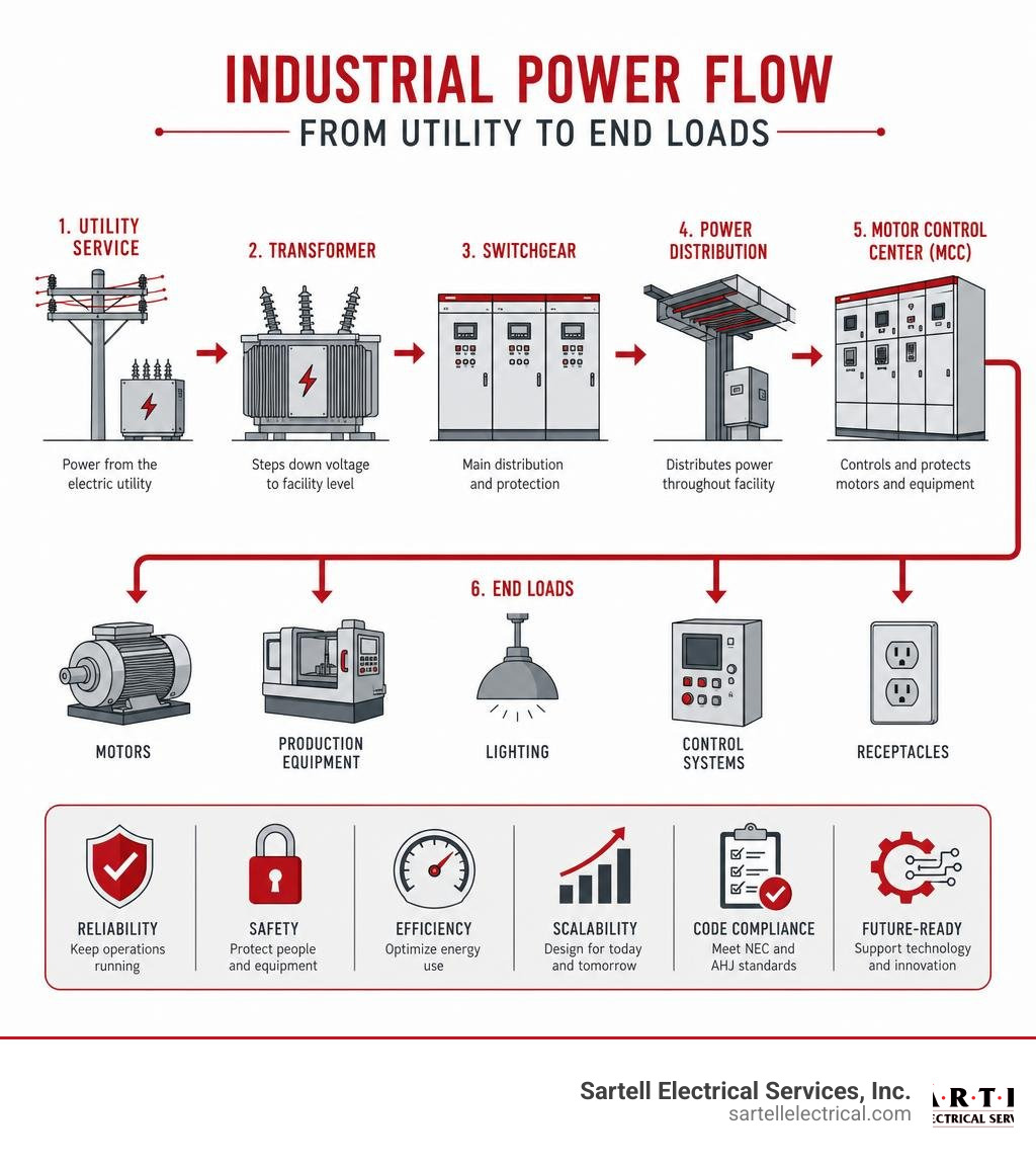
Similar topics to Industrial power distribution systems:
- electrical condition monitoring
- electrical switchgear maintenance
- industrial power monitoring system
Core Functions and Topologies of Industrial Power Distribution Systems
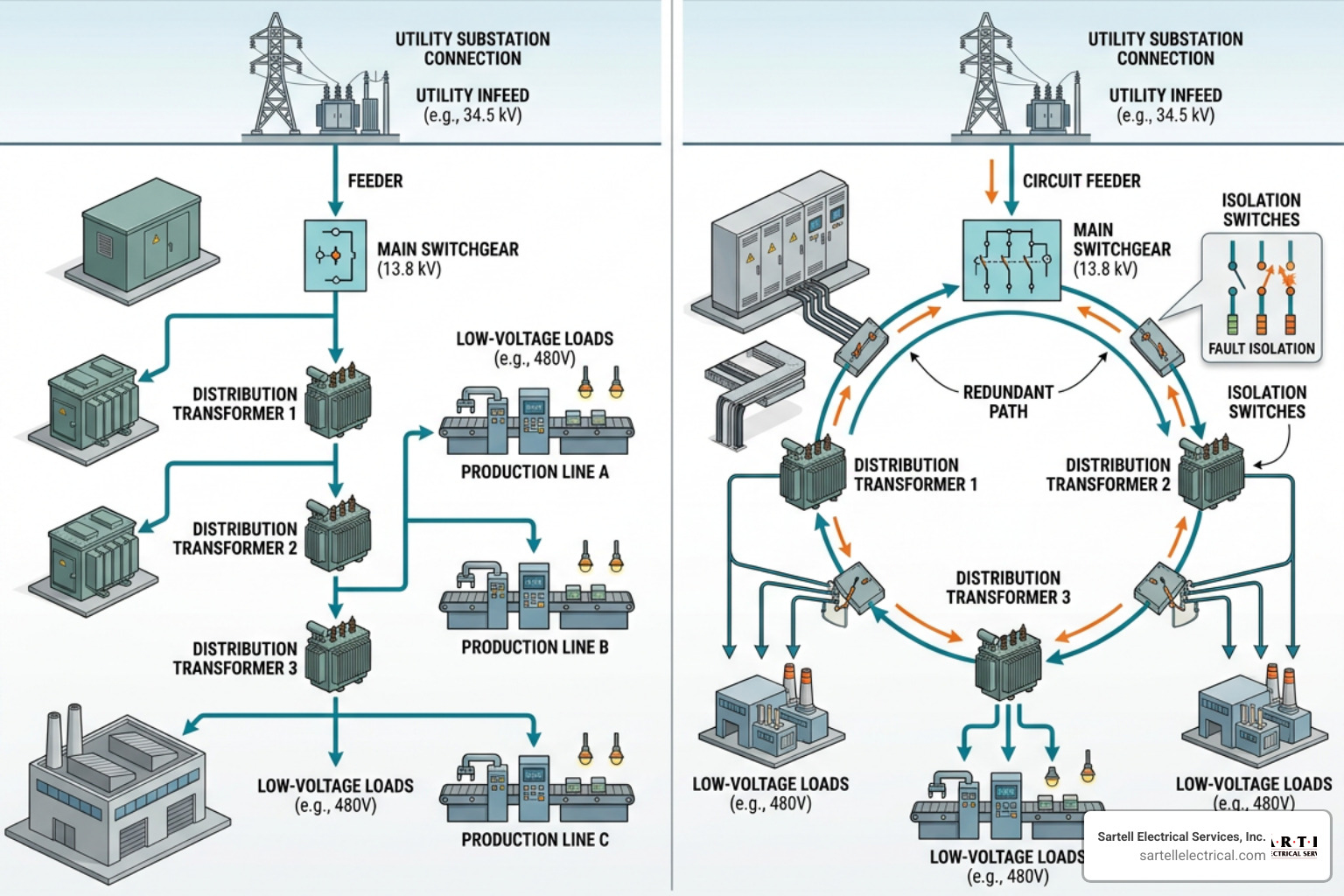
When we sit down to design or evaluate an electrical system for a facility in Boston, Worcester, or Reading, we start with the fundamentals: how power enters the facility, how it is transformed to usable levels, and how it is routed to ensure maximum uptime.
Industrial power distribution requires a careful balance of load distribution, voltage transformation, and ongoing power quality management. The foundation of this balance lies in the physical layout, or topology, of the system. Design standards, such as the IEEE Recommended Practice for Electric Power Distribution for Industrial Plants (commonly known as the IEEE Red Book), provide the framework for these configurations to ensure safe and efficient operation.
Radial, Loop, and Meshed Network Configurations
The layout you choose dictates both your upfront capital expenditure and your long-term operational reliability. There are three primary topologies used in industrial plants:
- Radial Systems: This is the most straightforward and common setup. Power flows from a single source, through a single path, to the end loads. While it is cost-effective and simple to design, any fault along the path can knock out everything downstream.
- Loop Systems: A loop configuration connects the power source in a ring around the facility. If a fault occurs in one section of the loop, switches can isolate that segment while power continues to flow to the remaining loads from the opposite direction. This significantly increases system redundancy.
- Meshed Networks: Highly complex and highly reliable, meshed networks feature multiple interconnected paths between sources and loads. If one path fails, power is instantly rerouted without interruption. This configuration is typically reserved for critical manufacturing processes where even a millisecond of downtime is unacceptable.
| Configuration | Reliability | Relative Cost | Complexity | Best For |
|---|---|---|---|---|
| Radial | Low to Moderate | Low | Low | Small facilities, non-critical loads |
| Loop | High | Medium | Medium | Medium to large plants, continuous processes |
| Meshed | Extremely High | High | High | Critical infrastructure, heavy manufacturing |
Primary Functions of Industrial Power Distribution Systems in Manufacturing
At its core, a well-designed system does much more than just hold wires together. It performs several critical functions simultaneously:
- Machinery Power Delivery: It delivers high-voltage, high-current power safely to large motors, compressors, and process lines.
- Load Balancing: It distributes electrical loads evenly across phases to prevent voltage imbalances that can overheat motors and degrade equipment.
- Operational Continuity: It isolates faults locally so that a problem on one assembly line doesn't cause a total plant blackout.
- Downtime Prevention: By integrating smart monitoring and redundant pathways, it ensures that maintenance can be performed without halting production.
Key Components of Modern Electrical Infrastructure
Modern electrical infrastructure relies on a network of heavy-duty equipment designed to handle massive thermal and mechanical stresses. If one component fails, the entire system is put at risk. That is why routine testing and Industrial Electrical Equipment Repair are vital parts of facility management.

Transformers and Bus Ducts in Industrial Power Distribution Systems
Transformers are the workhorses of the system, stepping down high utility voltages (such as 13.8kV) to safer, usable levels (like 480V).
- Liquid-Filled Transformers: Often installed outdoors, these use dielectric oil for cooling. They are highly efficient and have a long lifespan but require containment systems to prevent oil leaks.
- Dry-Type Transformers: Typically installed indoors, these rely on air circulation for cooling. They are safer for indoor environments because they eliminate fire hazards associated with oil.
- K-Rated Transformers: Modern industrial plants are packed with non-linear loads like variable frequency drives (VFDs) and computers. These loads create harmonics that overheat standard transformers. K-rated transformers are specifically designed to handle these harmonic currents without degrading.
To move these massive amounts of current from the transformer to the main distribution boards, we use bus ducts (or busways) rather than traditional cable and conduit. Bus ducts utilize heavy copper or aluminum conductors enclosed in a protective metal housing. They save space, reduce installation time, and offer excellent heat dissipation.
Switchgear, Circuit Breakers, and Enclosures
Once power reaches the building, it must be safely controlled and distributed. This is where switchgear and circuit breakers come into play.
- Metal-Clad Switchgear: This equipment houses circuit breakers, protective relays, and busses in separate, grounded metal compartments. This design provides maximum safety for operators and prevents faults from spreading between sections.
- Motor Control Centers (MCCs): An MCC centralizes all motor starters, variable frequency drives, and overload relays into a single modular enclosure, making troubleshooting and maintenance much easier.
- Air Circuit Breakers (ACBs): Used for main low-voltage distribution, ACBs handle high currents and provide robust overcurrent protection.
The physical enclosures protecting these components must be matched to their environment. Modular main distribution boards, such as those detailed in the System pro E power - Modular Main Distribution Boards Enclosures - Main distribution boards (ABB Enclosures) specifications, offer flexible, high-protection ratings (like IP65 or NEMA 12/4) to shield sensitive electronics from dust, moisture, and accidental contact on the factory floor.
Voltage Levels, Transformation, and Power Quality Management
To design an efficient system, you must match the voltage level to the load requirements. Operating large motors at low voltages requires massive conductors and results in high energy losses. Conversely, running small electronics on high-voltage lines is impractical and dangerous.
To keep a close eye on these dynamics, many forward-thinking facilities implement a dedicated Industrial Power Monitoring System to track voltage, current, and power quality metrics in real time.
Standard Voltage Levels and Transformer Sizing
Industrial facilities typically utilize a multi-tiered voltage structure:
- Primary Distribution: Power enters the facility at medium voltages (commonly 4.16kV to 13.8kV) and is routed to localized substations.
- Secondary Distribution: Localized transformers step this power down to 480V three-phase for heavy machinery and motors, 208V three-phase for smaller equipment, and 120/240V single-phase for standard office outlets and lighting.
When sizing transformers, we don't just add up the nameplate horsepower of every machine. We apply demand factors to account for the fact that not all machines run at full load simultaneously. However, we also build in a healthy growth margin (typically 20% to 30%) to accommodate future equipment additions without requiring an expensive transformer upgrade down the line.
Mitigating Power Quality Issues in Industrial Power Distribution Systems
Power quality issues can quietly destroy electronic components and inflate your utility bills. The most common culprits include:
- Voltage Sags: Brief drops in voltage, often caused by starting large motors. These can cause sensitive control systems to reset, halting production.
- Harmonics: Electrical noise generated by VFDs, LED lighting, and switching power supplies. Harmonics overheat motors and transformers.
- Poor Power Factor: A measure of how effectively your facility uses electrical power. If your power factor is low, you are drawing more current than necessary, which strains the grid and results in heavy utility penalties.
We mitigate these issues using capacitor banks for power factor correction and active or passive harmonic filters to clean up electrical noise, ensuring a stable environment for your machinery.
Protection, Control, and Safety Schemes
Safety is not an afterthought in electrical design; it is the absolute priority. A fault in an industrial system can release immense amounts of energy, risking lives and destroying equipment.
Keeping your system safe requires adherence to strict safety standards, as outlined in our Industrial Electrical Maintenance Complete Guide.
Selective Coordination and Fault Isolation
If a fault occurs on a small conveyor belt motor in the back corner of your plant, you don't want the main breaker for the entire facility to trip.
Selective coordination is the practice of matching the speed and trip settings of upstream and downstream circuit breakers. By analyzing the time-current curves of each breaker, we design the system so that the breaker closest to the fault trips first. This isolates the problem to a single branch circuit while keeping the rest of the facility up and running. Advanced systems utilize zone selective interlocking (ZSI), where breakers communicate digitally to isolate faults even faster.
Arc Flash Mitigation and Surge Protection
An arc flash is a rapid, explosive release of energy caused by an electrical fault through the air. To protect workers, we must design systems that minimize incident energy levels.
- Maintenance Mode Switches: These temporarily adjust breaker settings to trip instantly if a fault is detected while an electrician is working on live equipment, drastically reducing potential arc flash energy.
- Current-Limiting Fuses: These open incredibly fast under high-fault conditions, interrupting the current before it can reach its peak value.
- Surge Protective Devices (SPDs): Installed at main distribution panels, SPDs protect sensitive digital controls and PLCs from high-voltage transients caused by lightning strikes or utility switching.
Designing for Reliability, Scalability, and Code Compliance
When designing industrial power distribution systems, we plan for two certainties: things will fail, and your business will grow.
To achieve high system availability, we design redundancy into the system. An N+1 redundancy scheme ensures that if you need "N" number of components (like transformers or generators) to run, you have one extra "+1" on standby. For critical facilities, a 2N architecture provides two completely independent, fully redundant power paths. Comprehensive design methodologies, such as those found in the Siemens TIP applications for power distribution manual, offer excellent guidance on implementing these redundant frameworks.
Code Compliance and Future Expansion
All installations must strictly comply with the National Electrical Code (NEC). Key considerations include:
- NEC Article 230.95: Requires ground-fault protection of equipment for service disconnects rated 1000 amperes or more on solidly grounded wye services.
- Conduit Fill Limits: Ensuring that wires have enough physical space within conduits to dissipate heat safely.
- Spare Capacity: Designing panels and raceways with physical space and electrical capacity for future breakers and feeders.
Installation, Commissioning, and Maintenance Best Practices
A great design on paper is only as good as its physical execution. Before energizing any new system, we perform rigorous commissioning and pre-energization testing:
- Insulation Resistance Testing (Megger Testing): Verifies that the insulation on cables and motor windings has not been damaged during installation.
- Grounding System Testing: Confirms that the facility has a low-resistance path to ground to safely dissipate fault currents.
- Infrared Thermography: Scanning panels under load to identify loose connections or unbalanced loads before they lead to a failure.
Establishing an ongoing preventative maintenance program, as detailed in our guide on Industrial Electrical Maintenance, is the single best way to maximize the lifespan of your electrical assets.
The Future of Industrial Power: Industry 4.0, Renewables, and DC Grids
The industrial electrical landscape is changing rapidly. The push for decarbonization and the rise of smart manufacturing are reshaping how plants manage their energy.
One of the most exciting developments is the shift toward direct current (DC) grids within industrial environments. As highlighted in the VDE SPEC 90037 V1.0 (en) - DC-INDUSTRIE framework, utilizing a centralized DC bus in manufacturing plants can improve energy efficiency by up to 10% by eliminating the need to repeatedly convert AC power to DC for variable speed drives, solar panels, and battery storage.
Integrating Renewable Energy and Energy Storage
Many Massachusetts facilities are integrating on-site solar photovoltaics (PV) and Battery Energy Storage Systems (BESS). These systems allow for:
- Peak Shaving: Drawing power from batteries during times of peak utility rates to lower demand charges.
- Decentralized Control: Allowing portions of the facility to operate as a "microgrid," running independently from the main utility grid during an outage.
Industry 4.0 and Digitalization in Power Monitoring
Modern switchgear is no longer just metal and copper; it is highly digital. By deploying IoT sensors, smart meters, and digital twins, facility managers can monitor the health of their entire system from a single dashboard.
Using advanced software, like a Power Plant Monitoring System, allows maintenance teams to transition from reactive troubleshooting to predictive maintenance — fixing components based on real-time health data before they ever have a chance to fail.
Frequently Asked Questions about Industrial Power Distribution Systems
What is the difference between radial and loop distribution systems?
A radial system features a single path from the power source to the load. It is cost-effective but offers no redundancy. A loop system forms a closed ring, allowing power to reach loads from two different directions. If a fault occurs, the affected section can be isolated while the rest of the facility remains powered, offering much higher reliability at a higher initial cost.
How does selective coordination improve facility uptime?
Selective coordination ensures that only the protective device closest to an electrical fault opens. By carefully calibrating the trip times and current settings of your circuit breakers, a fault on a localized machine will only trip its local breaker, preventing a cascading effect that could shut down the entire main distribution board or the whole facility.
Why is power factor correction important for industrial plants?
Industrial plants run many inductive loads, like electric motors and transformers, which draw both active power (kW) and reactive power (kVAR). A low power factor means your system is drawing excess current to do the same amount of work, straining your electrical infrastructure. Utilities charge heavy penalties for low power factor, so installing capacitor banks or active filters directly lowers your monthly utility bills.
Conclusion
Designing, maintaining, and upgrading industrial power distribution systems requires a deep understanding of electrical engineering principles, local safety codes, and modern technology. Whether you are expanding an existing production line in Andover, upgrading switchgear in Chelsea, or building a brand-new facility in Boston, partnering with an experienced electrical contractor is key to your project's success.
At Sartell Electrical Services, we bring over 30 years of hands-on experience to every project. Based in Reading, MA, we proudly serve commercial, industrial, telecom, and healthcare clients throughout Massachusetts, Essex County, Middlesex County, Norfolk County, Suffolk County, and the Greater Boston area. Our commitment to excellence, leadership, and customer service ensures that your electrical infrastructure is safe, reliable, and built to scale.
Ready to evaluate or upgrade your facility's power systems? Contact Sartell Electrical Services today to speak with our team of industrial electrical experts.
Why Quality Electrical Contracting Is the Foundation of Every Successful Project
Quality electrical contracting means more than just running wire and flipping breakers. It's the difference between a project that's safe, on time, and built to last — and one that creates costly problems down the road.
Here's a quick breakdown of what sets quality electrical contractors apart:
- Licensed and insured — verified credentials protect you from liability and ensure code compliance
- Proven experience — contractors with decades of project history deliver fewer surprises
- Clear communication — transparent timelines, updates, and pricing throughout the job
- Safety-first culture — rigorous protocols that protect workers and building occupants
- Code compliance — all work meets or exceeds local and national electrical standards
- Comprehensive services — from pre-construction planning through final inspection
Whether you're managing a commercial build-out, a healthcare facility upgrade, or a complex industrial installation, the contractor you choose directly affects your timeline, your budget, and your safety.
I'm Ed Sartell, President of Sartell Electrical Services, Inc., and I've spent nearly four decades delivering quality electrical contracting to homeowners, builders, and businesses across Massachusetts. That hands-on experience shapes everything we'll cover in this guide.
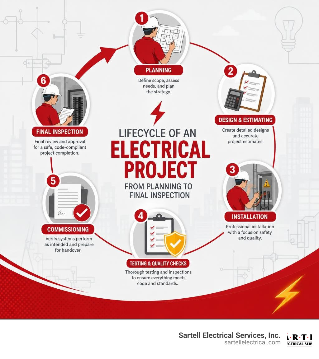
Simple guide to quality electrical contracting terms:
What Defines Quality Electrical Contracting?
When we talk about quality electrical contracting, we are referring to a comprehensive standard of practice. It is not simply about making sure the lights turn on when you flip a switch. True quality represents an alignment of technical mastery, rigorous safety protocols, administrative transparency, and structural reliability. In the electrical trade, shortcuts do not just lead to system failures—they lead to hazardous conditions like electrical fires and severe shock risks.
For any home, business, or industrial facility in Massachusetts, identifying a contractor who embodies these standards is the first step toward a successful installation. A premier contractor approaches every project with a long-term perspective, ensuring that the infrastructure installed today can handle the electrical loads of tomorrow. To understand how to evaluate these professionals without making costly mistakes, you can read our guide on How to Hire the Best Commercial Electrical Contractors Without Getting Zapped.

The Core Pillars of Quality Electrical Contracting
The foundation of exceptional electrical work rests on three core pillars:
- Uncompromising Workmanship: This involves neat, organized wiring, balanced panels, and structural integrity. A clean panel layout is not just aesthetically pleasing; it is essential for future troubleshooting and system safety.
- A Deep-Rooted Safety Culture: High-quality contractors do not view safety as a checklist item. It is integrated into daily tailgates, continuous field training, and strict adherence to protective gear standards.
- High Customer Retention: Companies that have been in business for decades report higher customer retention because they build relationships based on trust. When a contractor consistently delivers excellent commercial and residential solutions, clients do not feel the need to look elsewhere.
To find local professionals who adhere to these high standards, you can search the directory provided by the Find a Contractor – The Boston Chapter of the National Electrical ... .
Why Licensing and Insurance are Non-Negotiable
Hiring an unlicensed or uninsured individual to perform electrical work is one of the most significant risks a property owner can take. Licensing serves as official proof that an electrical contractor possesses the required training, field experience, and theoretical knowledge to execute complex electrical tasks safely.
Furthermore, adequate liability insurance and workers' compensation coverage protect you from financial ruin if an accident occurs on your property. If an uninsured worker is injured while performing installations, the property owner could be held liable. From a regulatory perspective, licensed contractors pull the necessary permits and schedule municipal inspections, ensuring full compliance with the law. For more details on federal safety requirements, you can review the OSHA Electrical Safety Standards and Regulations.
Comprehensive Electrical Services for Residential, Commercial, and Industrial Sectors
An experienced electrical contractor must be versatile. The electrical needs of a local homeowner differ vastly from those of a regional hospital or a heavy manufacturing plant. A high-quality contractor maintains specialized teams capable of addressing the unique engineering requirements of each sector. To learn more about these broad capabilities, check out our Commercial Electrical Services Ultimate Guide.
Residential vs. Commercial Electrical Needs
While both residential and commercial electrical systems rely on the same fundamental principles of physics, their scale, execution, and materials are entirely different. Residential systems typically utilize single-phase power, running through non-metallic sheathed cables behind drywall. Commercial systems, on the other hand, require three-phase power to support heavy machinery, large HVAC systems, and extensive lighting arrays. These systems are usually housed in protective metal conduits to withstand high-use environments.
| Feature | Residential Systems | Commercial Systems |
|---|---|---|
| Power Supply | Single-phase (120V/240V) | Three-phase (120V/208V or 277V/480V) |
| Wiring Method | Non-metallic sheathed cable (Romex) | Metal-clad (MC) cable or conduit |
| Load Requirements | Lower, intermittent household appliances | High, continuous machinery and HVAC loads |
| Safety Codes | Focuses heavily on GFCI/AFCI protection | Focuses on structural fire safety and emergency systems |
To keep your home safe from common hazards, the Electrical Safety Foundation International (ESFI) Home Safety offers excellent resources and checklists.
Specialized Industrial and Telecom Solutions
Industrial environments and telecommunications hubs demand a level of expertise that goes far beyond standard electrical wiring. Industrial contracting involves high-voltage power distribution, motor control centers, and heavy machinery hookups. These facilities require robust systems designed to run continuously without costly downtime.
In the telecom sector, contractors must manage delicate data cabling, fiber optics, server room power distribution, and backup generator systems. This work requires precision, as even a minor power fluctuation can corrupt critical data and disrupt communications across entire networks. If you are looking to understand how these advanced power systems are designed and installed, explore Powering Progress Finding Specialized Electrical Contractors in Boston.
Key Factors in Choosing the Right Electrical Contractor
Selecting the right partner for your project can feel overwhelming. With so many options available in Massachusetts, from local handymen to massive industrial firms, you must evaluate candidates systematically. Making the wrong choice can lead to project delays, budget overruns, and safety hazards. For a detailed guide on making this decision, consult our resource on Who to Call for Commercial Electrical Work in Boston.
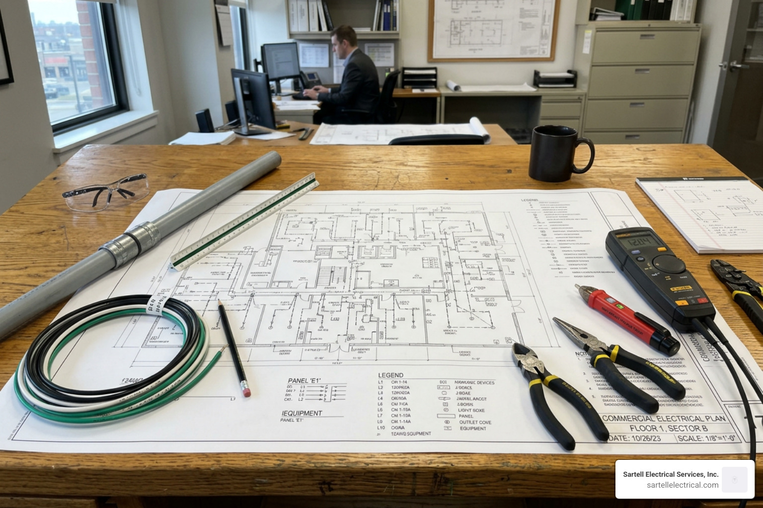
Evaluating Experience and Project Portfolios
When vetting an electrical contractor, look closely at their track record.
- Years in Business: Companies with over 30 years of experience have survived economic shifts by maintaining high standards and keeping clients happy.
- Active Project Volume: Contractors handling large-scale commercial or public works projects often manage millions of dollars in active project volume annually. This indicates they have the financial stability, manpower, and supply chain relationships to keep your project moving.
- Industry Standards: Reputable contractors align themselves with industry-leading organizations. You can learn more about these national benchmarks by visiting the National Electrical Contractors Association (NECA) Standards.
Energy Efficiency and Sustainable Electrical Design
Modern electrical contracting is not just about delivering power—it is about managing it intelligently. High-quality contractors help clients reduce their carbon footprints and lower utility bills through sustainable design. This includes implementing LED lighting retrofits, installing smart building automation systems, and setting up electric vehicle (EV) charging infrastructure.
By integrating energy-efficient solutions during the initial design phase, businesses can take advantage of local utility rebates and long-term operational savings. To see how these concepts are integrated into modern builds, read about our Commercial Electrical Design Build methodology.
Safety, Compliance, and Project Management Standards
A successful electrical project requires careful planning, disciplined execution, and continuous communication. From the moment the first conduit is bent to the final sign-off from the local inspector, every step must be managed with precision.
Why Quality Electrical Contracting Matters for Safety and Compliance
The National Electrical Code (NEC) is updated every three years to incorporate new safety findings and technological advancements. A premier electrical contractor ensures that their entire team undergoes regular training to stay up-to-date with these changes.
Failing to comply with local codes can result in failed inspections, delayed occupancy permits, and expensive retrofits. More importantly, code compliance is a matter of life safety. Proper grounding, correct wire sizing, and appropriate overcurrent protection devices prevent catastrophic system failures. To understand the safety codes that govern our industry, you can refer to the National Fire Protection Association (NFPA) Code Standards.
What to Expect During Project Communication
When you partner with a professional contracting firm, you should expect a structured, transparent communication process. This includes:
- Detailed Estimates: Clear, itemized breakdowns of material and labor costs.
- Dedicated Project Management: A single point of contact who coordinates schedules, manages field staff, and addresses your questions.
- Proactive Updates: Regular progress reports that keep you informed of any changes to the project timeline.
To learn more about how we manage communication and maintain high standards on our jobs, visit Sartell Electrical Services - Commercial Electrical Services.
Frequently Asked Questions about Electrical Services
How do electrical contractors handle emergency repairs and 24/7 service needs?
Electrical emergencies do not wait for business hours. Whether it is a sudden power outage at a manufacturing plant or a faulty breaker panel in a residential home, rapid response is crucial. Reputable contractors maintain dedicated service departments with stocked service vehicles and standby technicians ready to dispatch 24/7. These teams focus on quickly troubleshooting the issue, isolating the fault, and restoring safe, reliable power to minimize downtime. If you are facing an urgent electrical issue, you can reach out directly via Sartell Electrical Services - Contact Us.
What warranties or guarantees do reputable electrical contractors typically provide?
A quality contractor stands behind their work. Reputable electrical contracting firms typically offer a comprehensive warranty on their workmanship—often ranging from one to several years—in addition to passing along the manufacturer warranties on installed equipment (such as panels, generators, and lighting fixtures). This guarantee gives you peace of mind, knowing that if any issue arises due to installation errors, the contractor will return to resolve it promptly at no additional cost.
How do contractors ensure compliance with local building codes?
Ensuring compliance starts long before the tools are unpacked. It begins in the pre-construction phase, where engineers and master electricians review blueprints against local and national codes. Contractors handle the entire permitting process with local municipal offices and coordinate with town inspectors for rough-in and final inspections. Staying active in local trade associations helps contractors remain aware of regional amendments to the National Electrical Code. For a deeper look at navigating these regulations in our region, check out our Boston Electrical Contractors Ultimate Guide.
Conclusion
At Sartell Electrical Services, Inc., we believe that quality electrical contracting is built on a foundation of integrity, technical expertise, and outstanding customer service. For over 30 years, our team has been proud to serve communities across Massachusetts—including Middlesex, Essex, Norfolk, and Suffolk counties. From small residential upgrades in Reading to complex commercial and industrial installations in Greater Boston, we bring the same dedication to excellence to every single job.
When you choose to work with us, you are partnering with a team that prioritizes your safety, respects your budget, and delivers guaranteed results. To discuss your upcoming residential, commercial, or industrial project, visit our Electrical Contractor Service page and let us help power your vision.