

The 3 Way Switch Hook Up Diagram: What Every Homeowner Should Know First
A 3 way switch hook up diagram shows how to wire two switches so they control one light from two different locations — like the top and bottom of a staircase, or both ends of a long hallway.
Here's the quick answer:
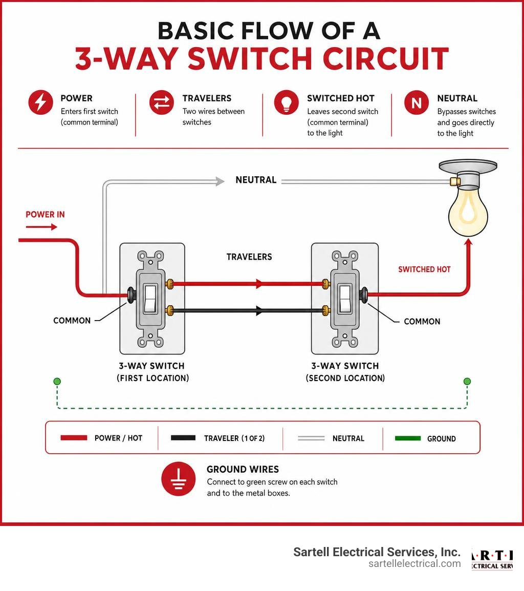
- Power (hot wire) enters the first switch box on the common terminal (dark screw)
- Two traveler wires (red and black) run between the two switches on the brass terminals
- The neutral wire bypasses both switches and runs straight to the light fixture
- The switched hot leaves the second switch's common terminal and goes to the light
- Ground wires connect to the green screw on each switch and to the metal boxes
That's the core of every standard 3-way circuit. The rest is just knowing which wire goes where — and doing it safely.
Walking across a dark room to hit a light switch is a small frustration. But miswiring a 3-way switch is a real problem — one that leaves lights that only work from one location, breakers that trip unexpectedly, or worse, a fire hazard hiding behind your wall plate. According to national data, over 51,000 home electrical fires occur every year in the U.S., with faulty wiring among the leading causes.
The good news: once you understand the diagram, the logic clicks fast.
I'm Ed Sartell, President of Sartell Electrical Services, and in nearly four decades of wiring homes and commercial buildings across Massachusetts, I've seen every variation of the 3 way switch hook up diagram — and every mistake that comes with it. This guide will walk you through each configuration clearly, so you know exactly what you're looking at before you touch a single wire.
What is a 3-Way Switch and How Does It Work?
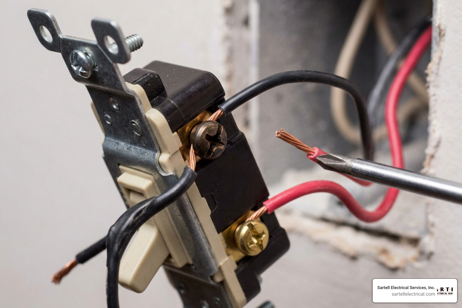
To understand how to wire these devices, it helps to understand what is happening inside the plastic housing. A standard light switch is a Single Pole Single Throw (SPST) device. It has two terminals: power comes in, and when you flip the switch, the internal contact closes to let power flow out to the light. It is a simple on/off gate.
A 3-way switch is a Single Pole Double Throw (SPDT) device. It does not have an "ON" or "OFF" label stamped on the toggle. Instead of simply opening and closing a single path, a 3-way switch redirects the electrical current down one of two paths.
Think of it like a train track switch. When you flip the toggle, you redirect the train (the electricity) from Track A to Track B. Because you have two of these switches connected together, flipping either switch will complete or break the circuit, regardless of the position of the other switch.
To see this mechanism in motion, you can watch this helpful How 3-Way Switches Work video.
To make this work, the switch uses three distinct screw terminals (plus a green grounding screw). Knowing which screw does what is the secret to reading any 3 way switch hook up diagram successfully. If you want a deep dive into identifying these terminals on a physical switch, check out our guide on 3-way light switch terminals.
Key Components of a 3-Way Circuit
Before we look at the schematic, let's identify the physical players in our electrical box:
- The Common Terminal (Dark Screw): This is the most important terminal on the switch. It is usually black or dark bronze. On the first switch, the incoming 120-volt "hot" power wire connects here. On the second switch, the "switched hot" wire (which carries power directly to the light fixture) connects here.
- The Traveler Terminals (Brass Screws): There are two brass-colored screws on every 3-way switch. These terminals connect the two switches to each other. It does not matter which traveler wire goes to which brass screw, as long as they run between the two switches.
- The Ground Screw (Green): This screw bonds the switch to your home's grounding system for safety.
- 14/3 NM-B Cable: This cable contains three insulated copper conductors (black, red, white) and one bare copper ground wire. It is used to run between the two switches to carry the traveler connections.
- 14/2 NM-B Cable: This cable contains two insulated copper conductors (black, white) and a bare ground. It is typically used to bring power from the service panel to the first switch, and to run from the second switch to the light.
Note: If your circuit is protected by a 15-amp breaker, you must use 14-gauge wire. If it is on a 20-amp breaker, you must use 12-gauge wire (12/2 and 12/3 NM-B). To learn more about selecting the right conductors, read our guide on wire for house wiring.
Understanding the 3 Way Switch Hook Up Diagram
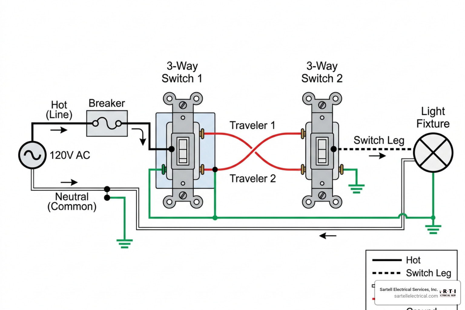
When you look at a 3 way switch hook up diagram, you will generally see one of two primary configurations. The difference between them comes down to one simple question: Where does the power source enter the circuit first?
In modern residential construction across Massachusetts, we almost always bring the power feed into one of the switch boxes first. However, in older homes throughout Boston, Reading, and the North Shore, you may find that the power source goes directly to the light fixture box first.
Understanding both configurations is crucial to avoiding a wiring headache.
| Feature / Configuration | Power-to-Switch First (Modern Standard) | Power-to-Light First (Older Homes) |
|---|---|---|
| Where Power Enters | First Switch Box | Light Fixture Box |
| Cable Between Switches | 14/3 NM-B (Travelers + Neutral) | 14/3 NM-B (Travelers + Switched Hot) |
| Neutral Location | Available in both switch boxes | Often terminates in the light box |
| Complexity | Straightforward, standard colors | Higher; requires re-identifying white wires |
| Smart Switch Ready | Yes (Neutral is easily accessible) | No (Requires rewiring or special smart switches) |
How to Read a 3 Way Switch Hook Up Diagram
To read a diagram like a pro, you must follow the path of the current.
- Line Hot (Black): Represents the constant, unswitched 120V power coming from the breaker panel.
- Load Hot (Black or Red): Represents the power going from the second switch to the light bulb.
- Travelers (Black & Red): Represent the two parallel paths connecting the switches.
- Neutral (White): Completes the circuit by returning current to the panel. It never connects to a standard 3-way switch terminal.
- Ground (Bare/Green): Provides a safe path for fault current.
For a comprehensive collection of alternative schematics, you can refer to the Three-Way Switch Diagram Guide.
Standard Power-to-Switch 3 Way Switch Hook Up Diagram
This is the most common setup you will encounter.
- Incoming Power: A 14/2 cable brings constant hot (black) and neutral (white) into the first switch box. The black wire connects directly to the dark common screw of Switch 1.
- Between the Switches: A 14/3 cable runs from the first box to the second box. The red and black wires connect to the brass traveler screws on both switches. The white wire is spliced directly to the incoming neutral using a wire nut (it bypasses Switch 1 completely).
- Outgoing Power: A 14/2 cable runs from the second switch box to the light fixture. The black wire (switched hot) connects to the dark common screw of Switch 2. The white wire is spliced to the white neutral wire coming from the first box.
- At the Light: The black switched hot connects to the gold terminal of the light, and the white neutral connects to the silver terminal.
For a visual breakdown of this specific configuration, you can view the How to Wire a 3-Way Switch Guide.
Step-by-Step Guide to Wiring a 3-Way Switch
Now that you understand the theory and have studied the 3 way switch hook up diagram, let's walk through the physical installation. If you are unfamiliar with general home wiring, we recommend reviewing the basics of standard residential electrical wiring before proceeding. You can also refer to the Family Handyman 3-Way Switch Guide for additional illustrations.
Preparing the Wires and Boxes
Before stripping any insulation, we have to make sure our electrical boxes aren't overcrowded. Under National Electrical Code (NEC) Article 314.16, we must perform "box fill calculations" to ensure there is enough physical space inside the box for all wires, clamps, and switches. Overcrowding boxes can cause wires to pinch, leading to short circuits or heat buildup.
Once you have verified your box size:
- Turn off the power: Shut off the circuit breaker at the main panel.
- Verify the power is off: Use a non-contact voltage tester inside both switch boxes to confirm there is zero electrical activity.
- Prep the cables: Strip about 6 inches of the outer sheathing off your NM-B cables.
- Strip the conductors: Use wire strippers to remove exactly 1/2 inch to 3/4 inch of insulation from the individual wire ends.
Making the Connections
With your wires prepped, it is time to make the physical connections. Remember to bend the exposed wire ends into a "C" hook shape and wrap them clockwise around the screw terminals. This ensures that as you tighten the screw, the loop closes tighter around the terminal.
-
Wire Switch 1:
- Connect the incoming black hot wire (from the breaker) to the dark common terminal.
- Connect the black and red traveler wires (from the 14/3 cable) to the two brass traveler terminals.
- Connect the bare copper ground wire to the green grounding screw.
- Join the white neutral wire from the power source to the white neutral wire of the 14/3 cable using a wire nut. Do not connect any neutral wires to the switch itself.
-
Wire Switch 2:
- Connect the outgoing black wire (going to the light) to the dark common terminal.
- Connect the black and red traveler wires (from the 14/3 cable) to the two brass traveler terminals.
- Connect the bare copper ground wire to the green grounding screw.
- Join the white neutral wire coming from Switch 1 to the white neutral wire going to the light fixture.
-
Ground Everything: If you are using metal junction boxes, you must run a ground pigtail from the ground splice to the box itself.
-
Secure and Protect: Wrap the sides of the switches with high-quality electrical tape to cover the exposed terminal screws. This provides an extra layer of protection when folding the wires back into the box.
For a detailed look at general switch installations, see our How to Wire a Switch Complete Wiring Guide.
Troubleshooting and Common Wiring Mistakes
Even experienced DIYers can make mistakes when wiring a 3-way circuit. In fact, three-way switch errors are among the most common troubleshooting calls we receive at Sartell Electrical Services.
Here are the most common issues and how to fix them:
- The Light Only Works in Certain Switch Positions: This is the classic "traveler-common mix-up." If you connect a traveler wire to the dark common terminal, or vice versa, the circuit will only complete when the other switch is flipped to a specific side. To fix this, use a multimeter or carefully trace your wires to ensure only the true line hot or load hot is connected to the dark common screws.
- The Circuit Breaker Trips Immediately: This usually happens when a neutral wire has been mistakenly connected to a switch terminal, creating a direct short circuit when the switch is flipped. Remember: standard 3-way switches do not use neutral connections.
- The Light Flickers or Sparks: Loose connections are a major fire hazard. Make sure all wire nuts are tight and that the terminal screws are firmly clamped down on the copper conductors.
If you are planning to add a dimmer to your 3-way setup, keep in mind that you cannot simply install two standard dimmers on the same 3-way circuit. Learn how to do this correctly by reading our guide on 3-way dimmer switch install.
Smart 3-Way Switches vs. Traditional Wiring
If you are upgrading to a smart home system, the rules of the 3 way switch hook up diagram change significantly. Smart switch installations have grown by over 35% year-over-year, but they require a different approach.
Unlike a mechanical switch, a smart switch contains computer chips, transmitters, and LED status lights. These components need constant power to run, even when the light is turned off. Because of this, 95%+ of modern smart switch installations require a dedicated neutral wire to complete the internal circuit.
Additionally, smart 3-way setups usually do not use traditional traveler wires to pass high-voltage current back and forth. Instead, they use a "Master" switch and an "Auxiliary" or "Add-on" companion switch. The companion switch communicates with the master switch via low-voltage signal lines or wireless protocols like Z-Wave or Wi-Fi.
If you live in an older home without neutral wires in your switch boxes, you aren't completely out of luck. Read our guide on The No-Neutral Solution for Your 2-Wire Dimmer Switch to explore your options.
Frequently Asked Questions About 3-Way Switches
Can I use a 3-way switch as a standard single-pole switch?
Yes, you can easily convert a 3-way switch for single-pole use. Simply connect your incoming hot wire to the dark common terminal and your outgoing load wire to one of the brass traveler terminals. Cap off the remaining unused brass traveler terminal with a wire nut or leave the screw tightened down empty.
Why do 3-way switches lack ON/OFF labels?
Because a 3-way switch controls a light from two locations, the physical position of the toggle switch does not correspond directly to whether the light is on or off. Flipping either switch changes the state of the circuit. Therefore, having "ON" or "OFF" labels would be misleading.
Do both 3-way switches require a neutral wire?
Under the current National Electrical Code (NEC Article 404.2(C)), a neutral wire is required at almost all switch locations to accommodate future electronic controls. However, in traditional mechanical wiring, the neutral wire simply passes through the switch boxes without connecting to the switches themselves.
Conclusion
Wiring a 3-way switch is a highly rewarding home improvement project, but it requires patience, attention to detail, and a strict adherence to safety codes. By following a proper 3 way switch hook up diagram, keeping your common and traveler wires straight, and ensuring your system is properly grounded, you can enjoy the convenience of multi-location lighting control with total peace of mind.
However, electrical work is not something to guess at. If you open your switch box and find a confusing web of wires, or if your home was built before modern color-coding standards, the safest choice is always to call in a professional.
At Sartell Electrical Services, we have been serving homeowners and businesses throughout Reading, MA, and the greater Boston area with a commitment to safety, leadership, and excellence. Whether you need help troubleshooting a faulty switch or want to upgrade your home to a modern smart lighting system, our team of licensed electricians is here to help.
Ready to get started? Check out our How to Wire a Switch Complete Wiring Guide for more expert tips, or contact us today to schedule your next service call!