Why Industrial Power Distribution Systems Are Critical to Modern Manufacturing
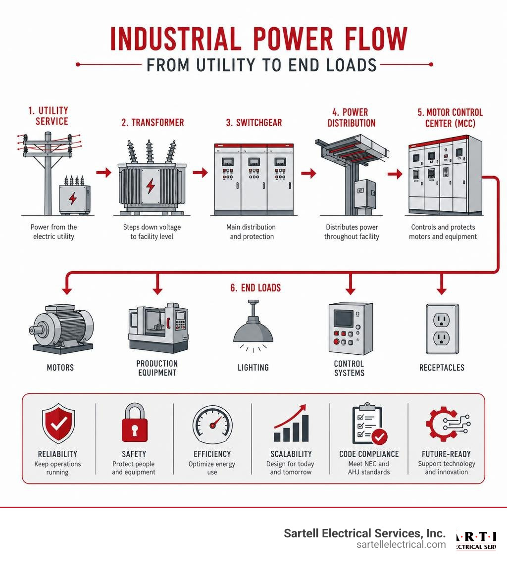
Industrial power distribution systems are the backbone of any manufacturing facility — they move electricity from the utility connection to every machine, motor, and control panel on the floor.
Here's what you need to know at a glance:
| Key Factor | What It Means for Your Facility |
|---|---|
| System topology | Radial, loop, or meshed — each offers different levels of reliability and cost |
| Voltage levels | Typically 480V three-phase for machinery, stepped down for lighting and controls |
| Key components | Transformers, switchgear, bus ducts, motor control centers, circuit breakers |
| Protection | Arc flash mitigation, overcurrent protection, selective coordination |
| Code compliance | Must meet NEC requirements and local authority having jurisdiction (AHJ) standards |
| Future-readiness | Scalable design accommodates renewables, energy storage, and Industry 4.0 integration |
A poorly designed power distribution system doesn't just cause nuisance trips — it leads to unplanned downtime, safety incidents, and costly retrofits that could have been avoided at the design stage. For industrial facilities, where a single line stoppage can cost thousands of dollars per hour, the stakes are high.
Getting the design right from the start means understanding your loads, your growth plans, your redundancy requirements, and the codes that govern all of it.
I'm Ed Sartell, President of Sartell Electrical Services, and since 1985 I've helped businesses across Massachusetts plan and install reliable industrial power distribution systems for commercial and industrial facilities of all sizes. In this guide, I'll walk you through everything you need to evaluate, design, and future-proof your electrical infrastructure.
Similar topics to Industrial power distribution systems:
- electrical condition monitoring
- electrical switchgear maintenance
- industrial power monitoring system
Core Functions and Topologies of Industrial Power Distribution Systems
When we sit down to design or evaluate an electrical system for a facility in Boston, Worcester, or Reading, we start with the fundamentals: how power enters the facility, how it is transformed to usable levels, and how it is routed to ensure maximum uptime.
Industrial power distribution requires a careful balance of load distribution, voltage transformation, and ongoing power quality management. The foundation of this balance lies in the physical layout, or topology, of the system. Design standards, such as the IEEE Recommended Practice for Electric Power Distribution for Industrial Plants (commonly known as the IEEE Red Book), provide the framework for these configurations to ensure safe and efficient operation.
Radial, Loop, and Meshed Network Configurations
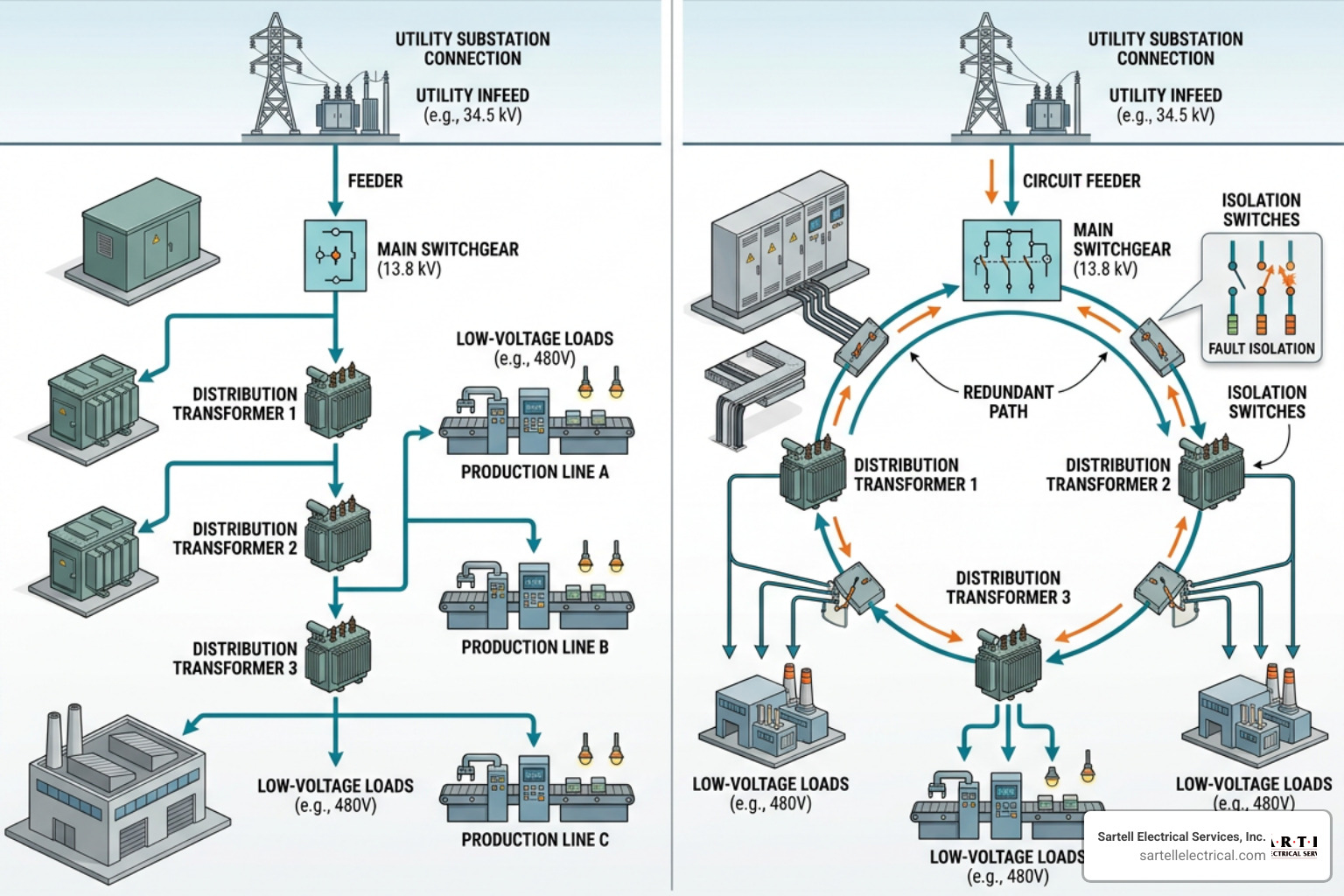
The layout you choose dictates both your upfront capital expenditure and your long-term operational reliability. There are three primary topologies used in industrial plants:
- Radial Systems: This is the most straightforward and common setup. Power flows from a single source, through a single path, to the end loads. While it is cost-effective and simple to design, any fault along the path can knock out everything downstream.
- Loop Systems: A loop configuration connects the power source in a ring around the facility. If a fault occurs in one section of the loop, switches can isolate that segment while power continues to flow to the remaining loads from the opposite direction. This significantly increases system redundancy.
- Meshed Networks: Highly complex and highly reliable, meshed networks feature multiple interconnected paths between sources and loads. If one path fails, power is instantly rerouted without interruption. This configuration is typically reserved for critical manufacturing processes where even a millisecond of downtime is unacceptable.
| Configuration | Reliability | Relative Cost | Complexity | Best For |
|---|---|---|---|---|
| Radial | Low to Moderate | Low | Low | Small facilities, non-critical loads |
| Loop | High | Medium | Medium | Medium to large plants, continuous processes |
| Meshed | Extremely High | High | High | Critical infrastructure, heavy manufacturing |
Primary Functions of Industrial Power Distribution Systems in Manufacturing
At its core, a well-designed system does much more than just hold wires together. It performs several critical functions simultaneously:
- Machinery Power Delivery: It delivers high-voltage, high-current power safely to large motors, compressors, and process lines.
- Load Balancing: It distributes electrical loads evenly across phases to prevent voltage imbalances that can overheat motors and degrade equipment.
- Operational Continuity: It isolates faults locally so that a problem on one assembly line doesn't cause a total plant blackout.
- Downtime Prevention: By integrating smart monitoring and redundant pathways, it ensures that maintenance can be performed without halting production.
Key Components of Modern Electrical Infrastructure
Modern electrical infrastructure relies on a network of heavy-duty equipment designed to handle massive thermal and mechanical stresses. If one component fails, the entire system is put at risk. That is why routine testing and Industrial Electrical Equipment Repair are vital parts of facility management.

Transformers and Bus Ducts in Industrial Power Distribution Systems
Transformers are the workhorses of the system, stepping down high utility voltages (such as 13.8kV) to safer, usable levels (like 480V).
- Liquid-Filled Transformers: Often installed outdoors, these use dielectric oil for cooling. They are highly efficient and have a long lifespan but require containment systems to prevent oil leaks.
- Dry-Type Transformers: Typically installed indoors, these rely on air circulation for cooling. They are safer for indoor environments because they eliminate fire hazards associated with oil.
- K-Rated Transformers: Modern industrial plants are packed with non-linear loads like variable frequency drives (VFDs) and computers. These loads create harmonics that overheat standard transformers. K-rated transformers are specifically designed to handle these harmonic currents without degrading.
To move these massive amounts of current from the transformer to the main distribution boards, we use bus ducts (or busways) rather than traditional cable and conduit. Bus ducts utilize heavy copper or aluminum conductors enclosed in a protective metal housing. They save space, reduce installation time, and offer excellent heat dissipation.
Switchgear, Circuit Breakers, and Enclosures
Once power reaches the building, it must be safely controlled and distributed. This is where switchgear and circuit breakers come into play.
- Metal-Clad Switchgear: This equipment houses circuit breakers, protective relays, and busses in separate, grounded metal compartments. This design provides maximum safety for operators and prevents faults from spreading between sections.
- Motor Control Centers (MCCs): An MCC centralizes all motor starters, variable frequency drives, and overload relays into a single modular enclosure, making troubleshooting and maintenance much easier.
- Air Circuit Breakers (ACBs): Used for main low-voltage distribution, ACBs handle high currents and provide robust overcurrent protection.
The physical enclosures protecting these components must be matched to their environment. Modular main distribution boards, such as those detailed in the System pro E power - Modular Main Distribution Boards Enclosures - Main distribution boards (ABB Enclosures) specifications, offer flexible, high-protection ratings (like IP65 or NEMA 12/4) to shield sensitive electronics from dust, moisture, and accidental contact on the factory floor.
Voltage Levels, Transformation, and Power Quality Management
To design an efficient system, you must match the voltage level to the load requirements. Operating large motors at low voltages requires massive conductors and results in high energy losses. Conversely, running small electronics on high-voltage lines is impractical and dangerous.
To keep a close eye on these dynamics, many forward-thinking facilities implement a dedicated Industrial Power Monitoring System to track voltage, current, and power quality metrics in real time.
Standard Voltage Levels and Transformer Sizing
Industrial facilities typically utilize a multi-tiered voltage structure:
- Primary Distribution: Power enters the facility at medium voltages (commonly 4.16kV to 13.8kV) and is routed to localized substations.
- Secondary Distribution: Localized transformers step this power down to 480V three-phase for heavy machinery and motors, 208V three-phase for smaller equipment, and 120/240V single-phase for standard office outlets and lighting.
When sizing transformers, we don't just add up the nameplate horsepower of every machine. We apply demand factors to account for the fact that not all machines run at full load simultaneously. However, we also build in a healthy growth margin (typically 20% to 30%) to accommodate future equipment additions without requiring an expensive transformer upgrade down the line.
Mitigating Power Quality Issues in Industrial Power Distribution Systems
Power quality issues can quietly destroy electronic components and inflate your utility bills. The most common culprits include:
- Voltage Sags: Brief drops in voltage, often caused by starting large motors. These can cause sensitive control systems to reset, halting production.
- Harmonics: Electrical noise generated by VFDs, LED lighting, and switching power supplies. Harmonics overheat motors and transformers.
- Poor Power Factor: A measure of how effectively your facility uses electrical power. If your power factor is low, you are drawing more current than necessary, which strains the grid and results in heavy utility penalties.
We mitigate these issues using capacitor banks for power factor correction and active or passive harmonic filters to clean up electrical noise, ensuring a stable environment for your machinery.
Protection, Control, and Safety Schemes
Safety is not an afterthought in electrical design; it is the absolute priority. A fault in an industrial system can release immense amounts of energy, risking lives and destroying equipment.
Keeping your system safe requires adherence to strict safety standards, as outlined in our Industrial Electrical Maintenance Complete Guide.
Selective Coordination and Fault Isolation
If a fault occurs on a small conveyor belt motor in the back corner of your plant, you don't want the main breaker for the entire facility to trip.
Selective coordination is the practice of matching the speed and trip settings of upstream and downstream circuit breakers. By analyzing the time-current curves of each breaker, we design the system so that the breaker closest to the fault trips first. This isolates the problem to a single branch circuit while keeping the rest of the facility up and running. Advanced systems utilize zone selective interlocking (ZSI), where breakers communicate digitally to isolate faults even faster.
Arc Flash Mitigation and Surge Protection
An arc flash is a rapid, explosive release of energy caused by an electrical fault through the air. To protect workers, we must design systems that minimize incident energy levels.
- Maintenance Mode Switches: These temporarily adjust breaker settings to trip instantly if a fault is detected while an electrician is working on live equipment, drastically reducing potential arc flash energy.
- Current-Limiting Fuses: These open incredibly fast under high-fault conditions, interrupting the current before it can reach its peak value.
- Surge Protective Devices (SPDs): Installed at main distribution panels, SPDs protect sensitive digital controls and PLCs from high-voltage transients caused by lightning strikes or utility switching.
Designing for Reliability, Scalability, and Code Compliance
When designing industrial power distribution systems, we plan for two certainties: things will fail, and your business will grow.
To achieve high system availability, we design redundancy into the system. An N+1 redundancy scheme ensures that if you need "N" number of components (like transformers or generators) to run, you have one extra "+1" on standby. For critical facilities, a 2N architecture provides two completely independent, fully redundant power paths. Comprehensive design methodologies, such as those found in the Siemens TIP applications for power distribution manual, offer excellent guidance on implementing these redundant frameworks.
Code Compliance and Future Expansion
All installations must strictly comply with the National Electrical Code (NEC). Key considerations include:
- NEC Article 230.95: Requires ground-fault protection of equipment for service disconnects rated 1000 amperes or more on solidly grounded wye services.
- Conduit Fill Limits: Ensuring that wires have enough physical space within conduits to dissipate heat safely.
- Spare Capacity: Designing panels and raceways with physical space and electrical capacity for future breakers and feeders.
Installation, Commissioning, and Maintenance Best Practices
A great design on paper is only as good as its physical execution. Before energizing any new system, we perform rigorous commissioning and pre-energization testing:
- Insulation Resistance Testing (Megger Testing): Verifies that the insulation on cables and motor windings has not been damaged during installation.
- Grounding System Testing: Confirms that the facility has a low-resistance path to ground to safely dissipate fault currents.
- Infrared Thermography: Scanning panels under load to identify loose connections or unbalanced loads before they lead to a failure.
Establishing an ongoing preventative maintenance program, as detailed in our guide on Industrial Electrical Maintenance, is the single best way to maximize the lifespan of your electrical assets.
The Future of Industrial Power: Industry 4.0, Renewables, and DC Grids
The industrial electrical landscape is changing rapidly. The push for decarbonization and the rise of smart manufacturing are reshaping how plants manage their energy.
One of the most exciting developments is the shift toward direct current (DC) grids within industrial environments. As highlighted in the VDE SPEC 90037 V1.0 (en) - DC-INDUSTRIE framework, utilizing a centralized DC bus in manufacturing plants can improve energy efficiency by up to 10% by eliminating the need to repeatedly convert AC power to DC for variable speed drives, solar panels, and battery storage.
Integrating Renewable Energy and Energy Storage
Many Massachusetts facilities are integrating on-site solar photovoltaics (PV) and Battery Energy Storage Systems (BESS). These systems allow for:
- Peak Shaving: Drawing power from batteries during times of peak utility rates to lower demand charges.
- Decentralized Control: Allowing portions of the facility to operate as a "microgrid," running independently from the main utility grid during an outage.
Industry 4.0 and Digitalization in Power Monitoring
Modern switchgear is no longer just metal and copper; it is highly digital. By deploying IoT sensors, smart meters, and digital twins, facility managers can monitor the health of their entire system from a single dashboard.
Using advanced software, like a Power Plant Monitoring System, allows maintenance teams to transition from reactive troubleshooting to predictive maintenance — fixing components based on real-time health data before they ever have a chance to fail.
Frequently Asked Questions about Industrial Power Distribution Systems
What is the difference between radial and loop distribution systems?
A radial system features a single path from the power source to the load. It is cost-effective but offers no redundancy. A loop system forms a closed ring, allowing power to reach loads from two different directions. If a fault occurs, the affected section can be isolated while the rest of the facility remains powered, offering much higher reliability at a higher initial cost.
How does selective coordination improve facility uptime?
Selective coordination ensures that only the protective device closest to an electrical fault opens. By carefully calibrating the trip times and current settings of your circuit breakers, a fault on a localized machine will only trip its local breaker, preventing a cascading effect that could shut down the entire main distribution board or the whole facility.
Why is power factor correction important for industrial plants?
Industrial plants run many inductive loads, like electric motors and transformers, which draw both active power (kW) and reactive power (kVAR). A low power factor means your system is drawing excess current to do the same amount of work, straining your electrical infrastructure. Utilities charge heavy penalties for low power factor, so installing capacitor banks or active filters directly lowers your monthly utility bills.
Conclusion
Designing, maintaining, and upgrading industrial power distribution systems requires a deep understanding of electrical engineering principles, local safety codes, and modern technology. Whether you are expanding an existing production line in Andover, upgrading switchgear in Chelsea, or building a brand-new facility in Boston, partnering with an experienced electrical contractor is key to your project's success.
At Sartell Electrical Services, we bring over 30 years of hands-on experience to every project. Based in Reading, MA, we proudly serve commercial, industrial, telecom, and healthcare clients throughout Massachusetts, Essex County, Middlesex County, Norfolk County, Suffolk County, and the Greater Boston area. Our commitment to excellence, leadership, and customer service ensures that your electrical infrastructure is safe, reliable, and built to scale.
Ready to evaluate or upgrade your facility's power systems? Contact Sartell Electrical Services today to speak with our team of industrial electrical experts.