What Are the Terminals on a 3-Way Light Switch?
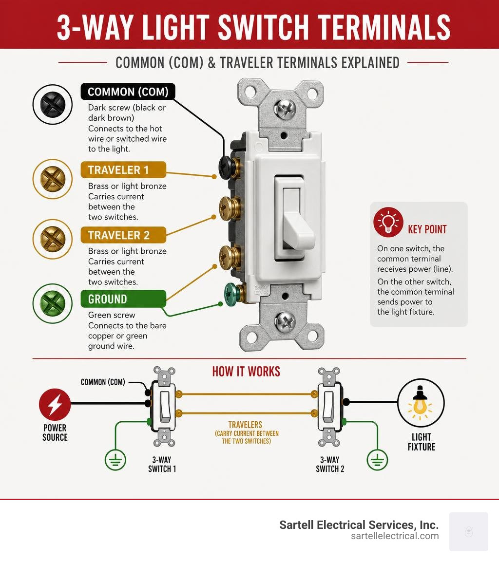
3-way light switch terminals are the three screw connections on the body of the switch that determine how your light is controlled from two separate locations. Here is a quick breakdown:
| Terminal | Color | Function |
|---|---|---|
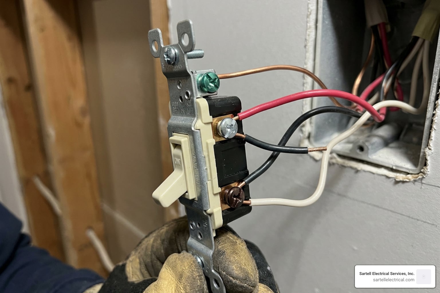
| Common (COM) | Dark (black or dark brown) | Connects to the hot wire or the switched wire going to the fixture |
| Traveler 1 | Brass or light bronze | Carries current between the two switches |
| Traveler 2 | Brass or light bronze | Carries current between the two switches |
| Ground | Green | Connects to the bare copper or green ground wire |
The common terminal is the most critical. On the first switch, it receives the incoming hot (line) wire. On the second switch, it sends power out to the light fixture.
The two traveler terminals connect to the wires that run between both switches, creating alternate paths for current depending on each switch's position.
If you have ever fumbled for a light switch at the bottom of a dark staircase or at the far end of a long hallway, you already understand exactly why 3-way switches exist. But when it comes time to wire or replace one, most homeowners hit a wall — the terminals are not labeled the way a standard single-pole switch is, and mixing them up means the light will only work from one location, or not at all.
I'm Ed Sartell, President of Sartell Electrical Services, and over nearly four decades of residential and commercial electrical work across Massachusetts, I have wired and troubleshot hundreds of 3-way light switch terminal configurations. In this guide, I will walk you through exactly how to identify each terminal, connect every wire correctly, and avoid the most common mistakes.
Understanding the Anatomy of 3 Way Light Switch Terminals
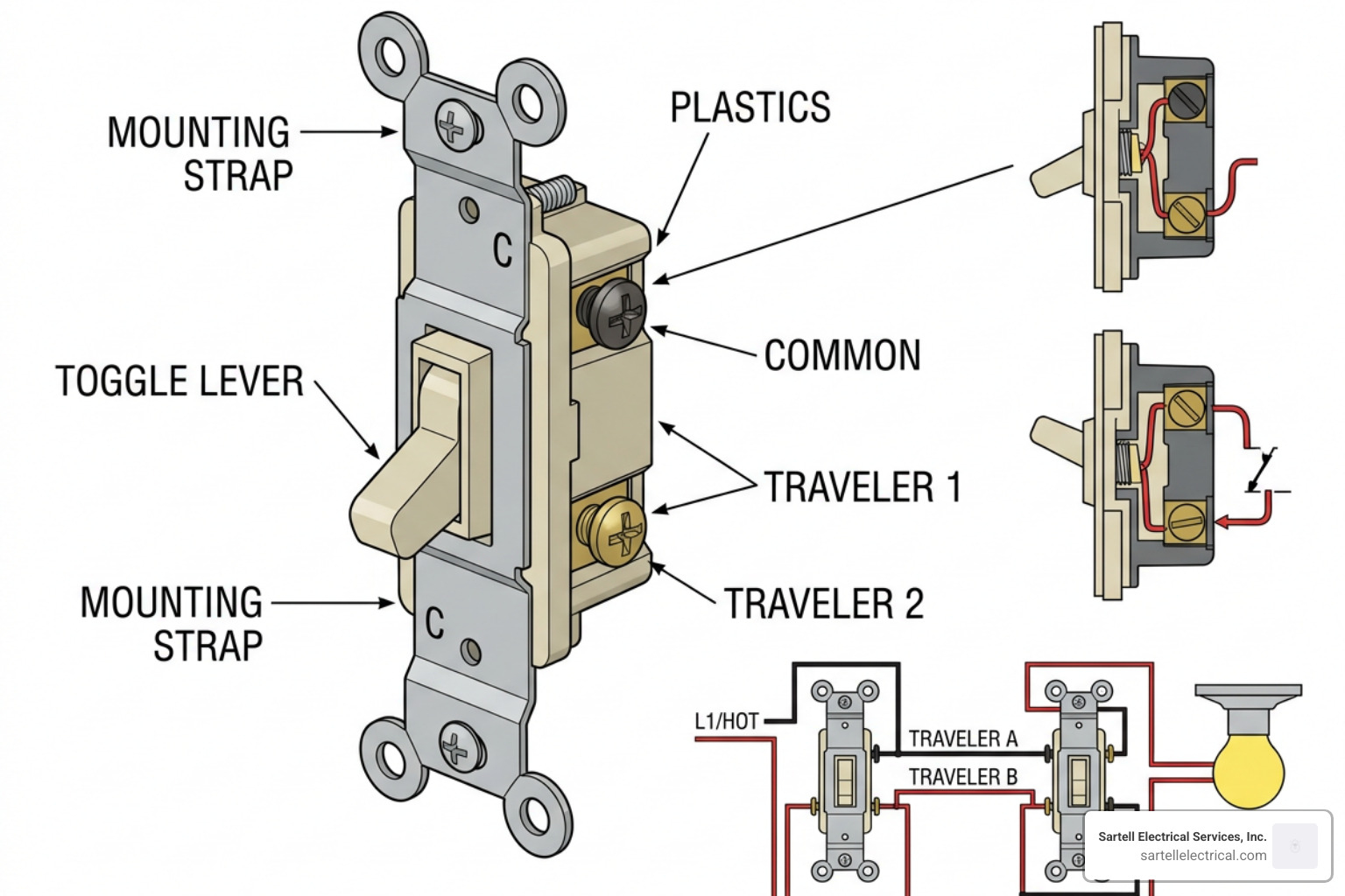
To understand how a 3-way switch operates, we must first look at its internal mechanics. Unlike a standard single-pole switch, which is a simple on/off single-pole single-throw (SPST) switch, a 3-way switch is a Single Pole Double Throw (SPDT) device.
This means that inside the switch, there is a single pathway (the pole, connected to the common terminal) that can toggle between two separate output pathways (the throws, connected to the traveler terminals). Because there is no dedicated "off" position, a 3-way switch toggle does not have "ON" or "OFF" embossed on the plastic. The state of the light fixture depends entirely on the relative positions of both switches in the circuit.
When you look at the physical body of a 3-way switch, you will observe four screw terminals:
- One dark-colored screw terminal: This is your common (COM) terminal.
- Two brass or lighter-colored screw terminals: These are your traveler terminals.
- One green screw terminal: Located on the metal yoke of the switch, this is the grounding terminal.
The physical arrangement of these screws varies widely between manufacturers like Leviton, Lutron, and Eaton. On some switches, the common screw is on the same side as one of the traveler screws; on others, it stands alone on one side. You cannot rely on physical location alone to identify them. Instead, you must look for the distinct color differences, or check the back of the switch body where the word "COMMON" is usually stamped into the plastic.
To help visualize how these terminals differ from standard switches, we have put together a comparison:
| Feature | Single-Pole Switch | 3-Way Switch |
|---|---|---|
| Number of Terminals | 2 screw terminals + 1 ground | 3 screw terminals + 1 ground |
| Terminal Colors | 2 brass/silver + 1 green | 1 dark black/copper, 2 brass + 1 green |
| ON/OFF Markings | Yes | No |
| Internal Mechanism | Single Pole Single Throw (SPST) | Single Pole Double Throw (SPDT) |
| Control Locations | One location only | Two locations |
For a broader look at how different switches are configured across residential applications, you can read more in our How to Wire a 3-Way Switch guide.
Identifying the Common Screw on 3 Way Light Switch Terminals
The common screw is the quarterback of the 3-way circuit. It is always a darker shade than the traveler screws — usually black, dark charcoal, or dark copper.
Its role changes depending on which side of the circuit the switch sits:
- At the first switch (Line Side): The common terminal receives the constant, unswitched hot power wire coming directly from your electrical panel.
- At the second switch (Load Side): The common terminal connects to the "switch leg" (the hot wire that runs directly up to the light fixture).
If you get nothing else right during a DIY project, you must ensure that your line-in hot and your load-out hot are connected to these dark common screws. If you accidentally hook a traveler wire to a common screw, you will break the logic of the circuit.
For a deeper dive into how multiple switches interact to control home lighting, check out our guide on Wiring Wonders: Connecting Two Light Switches for Seamless Control.
Connecting Traveler Wires to 3 Way Light Switch Terminals
The two brass-colored screws on your switch are the traveler terminals. These screws serve as the highway system between your two switch boxes.
When you flip the toggle on Switch 1, you redirect the electricity from Traveler Terminal A to Traveler Terminal B. If Switch 2 is toggled to receive power from Traveler Terminal B, the circuit completes, and the light turns on. Because these traveler wires simply carry current back and forth between the two switches, they are interchangeable. If you swap Traveler 1 and Traveler 2 on the brass screws of either switch, the system will still function perfectly.
We typically use a three-conductor cable (such as 14/3 or 12/3 NM-B) to run between the two switch boxes. This cable contains a black wire, a red wire, a white wire, and a bare copper ground. In a standard setup, the black and red wires are utilized as your travelers and connect directly to the brass traveler terminals on both switches.
To explore more about traveler routing and cable specifications, see the classic 3-Way Switch Wiring: A Step-by-Step Guide - Bob Vila article.
Essential Tools and Safety Protocols for Wiring

Before you touch a single wire or loosen a terminal screw, we must emphasize safety. Working with electricity carries risk, but following standard safety protocols minimizes those hazards.
First, always turn off the power at your home's main service panel (breaker box). Do not rely on the wall switch being in the "off" position, because as we established, 3-way switches do not have a true off position. Use a reliable non-contact voltage tester to verify that the wires inside the box are completely dead. Test every single wire in the box, not just the ones connected to the switch you are replacing.
Here is a list of the essential tools and materials we recommend having on hand:
- Non-contact voltage tester: To verify the circuit is de-energized.
- Wire strippers: For removing insulation from 14-gauge or 12-gauge conductors.
- Screwdrivers: Both flathead and Phillips head (or a square-drive Robertson screwdriver).
- Electrical tape: Essential for re-marking white wires used as hot conductors.
- Wire nuts or lever-lock connectors: To securely tie neutral and ground wires together.
- 14/3 NM-B cable (for 15-amp circuits) or 12/3 NM-B cable (for 20-amp circuits).
As of the latest updates, including the National Electrical Code (NEC) standards, a neutral wire is now required in almost all switch boxes in habitable rooms. This rule ensures that if you decide to upgrade to smart switches or smart dimmers in the future, you have the necessary neutral conductor available to power the switch's internal wireless transmitter.
When we wire these circuits, we must bypass the switches with our neutral wires, capping them together so they can run straight to the light fixture. If you are preparing to tackle this project, you can review safety checklists in this How to Wire a 3-Way Switch: Step-by-Step Guide With Diagrams | Build Coded resource.
Step-by-Step Guide to Wiring a 3-Way Switch Circuit
There are two primary ways a 3-way circuit is wired in Massachusetts homes: Power-to-Switch First (the most common modern setup) and Power-to-Light First (often found in older homes, sometimes referred to as a switch loop).
Let's walk through the step-by-step process for the standard Power-to-Switch First configuration, where the 120V power feed enters the first switch box, a 3-wire cable connects the two switches, and a 2-wire cable runs from the second switch box to the light.
Step 1: Prep and Identify Your Wires
Strip approximately 1/2 inch of insulation from the ends of your wires. In your first switch box, you should have the 2-wire feed (black hot, white neutral, bare ground) and the 3-wire traveler cable (black, red, white, bare ground). In the second box, you will have the 3-wire traveler cable and the 2-wire cable going to the light.
Step 2: Wire the First Switch (Power Input Side)
Connect the incoming black hot wire (from your breaker panel) directly to the dark common terminal on Switch 1. Next, take the black and red wires from your 3-wire cable and connect them to the two brass traveler terminals. Wire-nut the two white neutral wires together so they bypass the switch completely.
Step 3: Wire the Second Switch (Light Side)
Take the black wire from the 2-wire cable (the one running up to the light fixture) and connect it to the dark common terminal on Switch 2. Connect the red and black wires from your 3-wire traveler cable to the two brass traveler terminals. Just like in the first box, splice the white neutral wires together so they pass through to the light.
Step 4: Re-Marking White Wires (If Applicable)
If you are working on an older home with a "switch loop" configuration where a white wire must be used to carry hot current, the NEC requires you to re-identify that white wire. Wrap black or red electrical tape around the exposed white insulation near the terminal to signal to future electricians that this wire is a switched hot, not a neutral.
Step 5: Grounding Connections
For safety, we must always ground our switches. Connect the bare copper or green ground wires together in each box, use a pigtail to connect to the green grounding screw on each switch, and if you are using metal junction boxes, ensure the box itself is bonded to the ground network.
For more information on adding dimming capabilities to this setup, see our guide on Wiring Wonders: Installing Your 3-Way Dimmer Switch Like a Pro.
Troubleshooting and Testing Your 3-Way Switch Connections
Once everything is tucked back into the boxes and the faceplates are secured, restore power at the breaker panel. It's time to test your work.
To properly test a 3-way setup, walk to Switch A and turn the light on, then walk to Switch B and turn it off. Repeat this test in every possible toggle combination. If your light can be turned on and off independently from both locations, congratulations! You have wired it successfully.
However, if your light only works when one of the switches is in the "UP" position, you have a classic crossed traveler error. This occurs when you accidentally swap the common wire with one of the traveler wires on either Switch A or Switch B.
Here is how we diagnose and fix this:
- Turn off the power and verify with your voltage tester.
- Open both switch boxes and inspect the dark common screws.
- Verify that the common screw on Switch 1 has the actual hot feed from the panel, and the common screw on Switch 2 has the wire running to the light.
- If you find a red or black traveler wire connected to a common screw, swap it back to its correct brass traveler terminal.
If you are using modern LED bulbs and notice they are flickering or "ghosting" (glowing faintly even when the switch is off), this is usually caused by induced voltage. Because the traveler wires run parallel to each other over long distances inside your walls, a small amount of electromagnetic current can bleed from the hot traveler to the dead traveler, which is sometimes enough to light up sensitive LED bulbs. Installing a load capacitor or switching to high-quality, brand-name dimmers can solve this issue.
You can read more about resolving these dual-switch issues in our article Dimmer Duos: Can You Really Use Two Dimmers on One 3-Way Switch?.
Frequently Asked Questions about 3-Way Switch Terminals
Can I use a 3-way switch as a standard single-pole switch?
Yes, you can easily use a 3-way switch for a standard single-pole application. To do this, connect your incoming hot wire to the dark common terminal and your switched hot wire to one of the brass traveler terminals. Leave the second brass traveler terminal completely empty. Just keep in mind that because 3-way switches do not have "ON/OFF" markings, the toggle direction might feel backward depending on which traveler terminal you chose.
Why does my 3-way light only turn on when the other switch is in a specific position?
This is the most common symptom of a miswired 3-way switch. It means that the incoming hot wire (or the wire going to the light) was accidentally connected to one of the brass traveler terminals instead of the dark common terminal. When this happens, the circuit path is interrupted unless the other switch is toggled to match the exact traveler that is acting as the common. Double-check your common screws to resolve this.
Does a 3-way switch require a neutral wire under the 2026 NEC?
Yes, under modern NEC Article 404 rules, a neutral wire must be present in almost all switch boxes in new construction or during major renovations. While traditional, mechanical 3-way switches do not connect to or use the neutral wire themselves, the code requires the neutral to be capped and available in the box to support future smart home switches, which require a neutral to power their internal smart chips.
Conclusion
Understanding 3-way light switch terminals is the key to mastering multi-location lighting in your home. By taking the time to identify the dark common screw and keeping your traveler wires separated on the brass screws, you can safely install or replace your switches with confidence.
However, we know that electrical wiring can sometimes be tricky — especially in older Massachusetts homes with complex switch loops, plaster walls, or crowded junction boxes. If you run into any issues, or if you simply prefer to leave the electrical work to the professionals, we are here to help.
Sartell Electrical Services has been serving homeowners and businesses in Reading, MA, and across Middlesex, Essex, Norfolk, and Suffolk counties for over 30 years. Contact us today for a free quote on your next lighting project, and be sure to check out our How to Wire a Switch Complete Wiring Guide for more expert tips!