How Power Actually Gets From the Grid to Your Front Door
Power distribution systems are the final link in the electricity delivery chain — moving power from high-voltage transmission lines down to a usable voltage at your home or business.
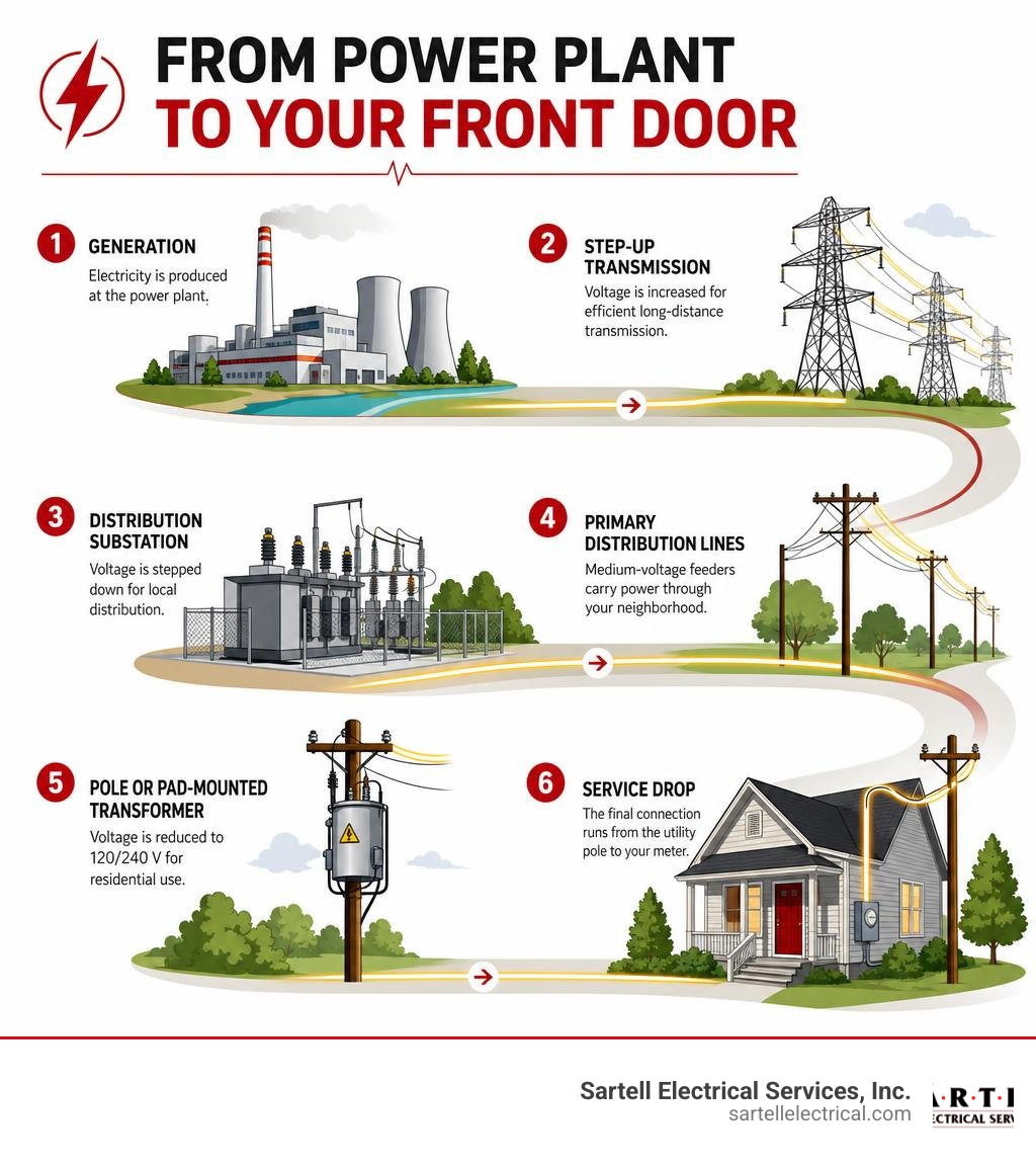
Here is a quick overview of how the process works:
- Generation — A power plant produces electricity at medium voltage.
- Step-up transmission — Transformers boost voltage to 44 kV–765 kV for efficient long-distance travel.
- Distribution substation — Voltage is stepped down to 2 kV–35 kV for local delivery.
- Primary distribution lines — Medium-voltage feeders carry power through your neighborhood.
- Pole or pad-mounted transformer — Voltage drops again to 120/240 V for residential use.
- Service drop — The final connection runs from the utility pole directly to your meter.
The system sounds simple. But behind every light switch is a remarkably complex web of substations, transformers, feeders, protective devices, and miles of wire — all engineered to keep power flowing safely and reliably, around the clock.
Distribution is not a small part of the picture, either. It accounts for roughly 32% of the total cost of electricity paid by U.S. consumers. And with 3,236 reported power outages recorded in 2013 alone — averaging 197 minutes each — how that infrastructure is designed and maintained matters enormously for businesses and homeowners alike.
I'm Ed Sartell, President of Sartell Electrical Services, and I've been working with power distribution systems at the commercial and residential level across Massachusetts since 1985. In this guide, I'll walk you through exactly how the grid works — from the substation to your service panel — so you can make smarter, more informed decisions about your electrical infrastructure.
Related content about Power distribution systems:
The Anatomy of Modern Power Distribution Systems

At its core, a power distribution system is designed to take bulk electrical energy from the high-voltage transmission network and safely deliver it to end-use equipment. Whether we are looking at a municipal utility in Middlesex County or a large industrial complex in Boston, MA, the fundamental anatomy of these systems remains remarkably consistent.
The system begins at the distribution substation. This critical facility houses the heavy machinery required to transition electricity from transmission-level voltages down to distribution levels. Within the substation, you will find busbars, power transformers, switchgear, and monitoring instruments that work in unison to control the flow of electricity.
From the substation, a network of primary feeders extends outward. These feeders can be overhead lines mounted on utility poles or underground cables buried beneath city streets. Feeders act as the primary highways of local power delivery, carrying medium-voltage power closer to residential neighborhoods, commercial districts, and industrial parks. Along these pathways, protective devices such as fuses, circuit breakers, and reclosers are strategically installed to isolate faults and prevent widespread blackouts.
For engineers and facility managers planning these layouts, the Electrical Distribution Fundamentals Design Guide Data Bulletin serves as an essential reference, detailing the standard physical and electrical parameters required to build a code-compliant, highly functional system.
Primary vs. Secondary Power Distribution Systems
To understand the modern grid, we must distinguish between the primary and secondary distribution systems.
The primary distribution system operates at medium voltage levels, typically ranging from 2 kV up to 35 kV phase-to-phase. This system is responsible for moving power over moderate distances from the substation to the immediate vicinity of the customer. In our service areas across Greater Boston, primary feeders usually run at 4 kV, 13.8 kV, or 34.5 kV. Large industrial facilities often purchase power directly at these primary medium voltages because they operate heavy machinery and maintain their own private substations.
The secondary distribution system operates at low voltage levels, delivering power directly to the customer’s electrical panel. For residential homes, this is typically the familiar 120/240V single-phase service. For commercial and light industrial buildings, we frequently design and service 208Y/120V or 488Y/277V three-phase systems.
To dive deeper into how these different voltage levels are utilized in commercial environments, you can read our comprehensive Power Distribution Systems Design Guide for Modern Industries.
The Role of Transformers in Power Distribution Systems
Without the humble transformer, modern electricity delivery would be economically impossible. Transformers utilize electromagnetic induction to change AC voltage levels with minimal energy loss. In power distribution systems, their primary job is the step-down function: reducing dangerous, medium-voltage primary power to safe, usable low-voltage secondary power.
However, operating these massive electromagnetic devices introduces unique physical challenges:
- Magnetizing Current: When a transformer is energized, it requires a small continuous current to maintain the magnetic field in its steel core.
- Inrush Currents: When a transformer is first switched on, it can draw a momentary surge of current up to 10 to 15 times its rated full-load current. This transient inrush must be carefully accounted for so it does not trip protective relays.
- Connection Groups (Vector Groups): Transformers are configured in specific winding arrangements, such as Delta-Wye ($Delta$-Y) or Wye-Wye (Y-Y). The choice of connection group determines phase displacement, grounding capabilities, and how harmonic currents are managed.
For those interested in the deep engineering mathematics behind transformer impedance, voltage drop formulas, and connection configurations, the Distribution Automation Handbook provides exhaustive technical documentation.
Network Topologies: Radial, Loop, and Meshed Configurations
The physical layout, or topology, of a distribution network directly dictates its cost, complexity, and reliability. Depending on whether we are servicing a suburban neighborhood in Andover or a high-density data center in Boston, different configurations are utilized.
| Topology Type | Initial Cost | Reliability Level | Redundancy | Typical Application |
|---|---|---|---|---|
| Radial | Low | Low to Moderate | None | Rural areas, residential suburbs |
| Loop (Ring) | Moderate | High | Single-fault tolerance | Commercial districts, schools |
| Meshed (Network) | Very High | Extremely High | Multi-fault tolerance | Downtown urban cores, critical facilities |
- Radial Feeders: This is the simplest and least expensive layout, structured like a tree. Power flows from a single source outward to the customers. If a tree branch falls on a radial line, everyone downstream of the fault loses power.
- Loop-Type Feeders: In a loop configuration, the feeder makes a complete circle, starting and ending at the substation (or connecting two separate substations). If a fault occurs, switches can isolate the damaged section while power is routed to the remaining customers from the opposite direction.
- Meshed Networks: The gold standard of reliability. In a meshed system, multiple primary and secondary lines are interconnected in a grid-like pattern, supplied by multiple transformers in parallel. If one or even two sources fail, power instantly flows through alternative paths without a single second of interruption.
Regional Voltage Variations and Historical Evolution
Have you ever wondered why North America uses a 120/240V split-phase system while Europe and most of the world use a 220-240V single-phase standard? The answer lies in the famous "War of the Currents" during the late 19th century.
Thomas Edison pioneered the first commercial direct current (DC) distribution system, launching the Pearl Street Station in lower Manhattan in 1882. Edison's system delivered low-voltage DC directly to customers. Because low-voltage DC could not travel more than a mile without massive voltage drop, it required frequent, small generating stations.
Nikola Tesla and George Westinghouse countered with alternating current (AC). By using transformers, AC power could be stepped up to extremely high voltages, transmitted over hundreds of miles with minimal loss, and then stepped down near the customer. AC quickly won the war because of these massive economies of scale.
In the United States, early incandescent light bulbs were designed to run on 110V to 120V for safety and filament durability. When the grid expanded, the U.S. chose to keep the 120V standard for safety, using a split-phase 120/240V transformer configuration to allow larger appliances (like dryers and ovens) to run on 240V.
Conversely, European countries built their grids later. They opted to double the primary residential voltage to 220-240V. This allowed them to deliver twice as much power over the same thickness of copper wire, saving immense infrastructure costs, albeit at a slightly higher safety risk.
Protecting the Grid: Circuit Breakers, Fuses, and Relays

When an electrical fault occurs — such as a tree branch shorting out two phases or a car hitting a utility pole — the resulting short-circuit current can be thousands of times higher than normal. Without rapid protection, equipment would literally melt, and fires would break out.
Modern protection schemes rely on a coordinated hierarchy of devices:
- Circuit Breakers: Large, automatic switches capable of safely interrupting massive short-circuit currents. High-quality modular hardware, such as the System pro E power (ABB Enclosures) or the SIVACON S8 power distribution boards | Siemens, are designed to house these critical breakers safely in commercial and industrial settings.
- Fuses: The simplest protection device. A small metal wire designed to melt and open the circuit when current exceeds a specific threshold. Fuses are highly reliable but must be manually replaced after they blow.
- Reclosers: Because roughly 80% of overhead distribution faults are temporary (like a passing branch brushing against a wire), reclosers act as smart circuit breakers. They open when a fault is detected, wait a few seconds for the fault to clear, and then automatically "reclose" to restore power.
- Sectionalizers: These are smart switches installed downstream of a recloser. They do not interrupt fault currents themselves; instead, they count the number of times the upstream recloser opens. If the fault persists after a set number of attempts, the sectionalizer opens during the "dead time" to isolate the damaged line, allowing the recloser to restore power to the rest of the loop.
- Protective Relays: The "brains" of the protection system. They monitor current, voltage, and frequency, sending trip signals to circuit breakers when anomalies are detected.
To understand how to maintain these protection devices and ensure they operate correctly during a fault, check out our Industrial Electrical Maintenance Complete Guide.
Substation Insulation Coordination and Overvoltage Protection
Primary distribution substations are highly vulnerable to overvoltages caused by lightning strikes, grid switching operations, and temporary system faults. To protect millions of dollars of equipment, engineers practice insulation coordination.
This process involves matching the dielectric strength (insulation level) of substation equipment with the expected overvoltages in the system. The primary line of defense is the surge arrester. Modern substations utilize zinc oxide (ZnO) surge arresters. Under normal voltages, these devices act as insulators. However, when a high-voltage lightning surge hits, the zinc oxide instantly becomes highly conductive, safely diverting the massive current to the ground grid before it can damage the substation transformers.
Voltage Regulation, Power Quality, and Modern Grid Challenges
As electricity travels down miles of distribution lines, it encounters natural resistance and reactance, leading to a phenomenon known as voltage drop. If the voltage drops too low, home appliances can malfunction and industrial motors can overheat.
Utilities are legally required to keep customer voltage within a tight range (typically $pm 5%$ of nominal voltage). To achieve this, we employ several voltage regulation technologies:
- On-Load Tap Changers (OLTC): Specialized mechanisms built into substation transformers that adjust the turn ratio of the windings on the fly, boosting or lowering voltage as demand changes.
- Line Voltage Regulators: Autotransformers installed along long rural feeders that automatically boost voltage back to nominal levels.
- Capacitor Banks: Installed on utility poles or within industrial facilities to provide reactive power support. By counteracting inductive loads (like motors and air conditioners), capacitors improve the overall power factor, reduce line losses, and raise local voltage.
Maintaining high power quality is critical for modern commercial operations. Sensitive electronics cannot tolerate voltage sags, swells, or harmonic distortions. Ensuring your facility has a robust, clean power supply starts with understanding your Critical Electrical System.
Urban, Suburban, and Rural Distribution Dynamics
The physical construction of a distribution system varies wildly depending on the local population density:
- Urban Areas: Characterized by extremely high load density. Because space is limited, urban distribution is almost entirely underground. While undergrounding protects cables from weather and falling trees, it is incredibly expensive, costing five to ten times more than building overhead lines.
- Suburban Areas: Typically a hybrid mix. Primary feeders are often overhead, while newer residential developments utilize underground secondary cables fed from green, pad-mounted transformers in front yards.
- Rural Areas: Characterized by low load density and vast distances. To keep costs down, rural systems rely almost exclusively on overhead lines. In extremely remote areas, utilities may even use Single-Wire Earth Return (SWER) systems, which use a single phase conductor and utilize the earth itself as the return path to minimize pole and wire costs.
Distributed Generation and Smart Grid Integration
The traditional "one-way street" grid model — where power flows exclusively from massive power plants down to consumers — is rapidly changing. Today, we are seeing the rise of distributed generation, with more than 90% of all distributed generation in the U.S. coming from solar power.
While clean energy is fantastic, integrating hundreds of solar arrays into local distribution networks introduces major technical challenges. On sunny afternoons, excess solar generation can cause power to flow backward through the system, creating voltage spikes that can damage household appliances.
To manage this, states like Massachusetts have adopted formal net metering policies, allowing customers to receive credit for the power they feed back into the grid. Additionally, many modern facilities are turning to microgrids — self-contained power systems with local generation and energy storage that can disconnect from the main utility grid and run independently during an outage.
If you are planning a high-reliability facility, such as a server farm or a hospital, integrating these technologies requires careful planning. Learn more about how we handle these complex power requirements in our guide to Data Center Power Planning.
Economics, Regulation, and Reliability of Grid Infrastructure
Maintaining and upgrading our nation's power grid is an astronomical financial undertaking. Since 2000, the utility industry has invested over $275 billion (in 2012 USD) on distribution networks alone. Looking forward through 2030, projected investments to modernize the distribution grid are expected to reach as high as $582 billion.
These investments are heavily regulated. In Massachusetts, the Department of Public Utilities (DPU) acts as the public utility commission, regulating the rates that investor-owned utilities can charge consumers. They must balance the utility's need to recover infrastructure costs with the public's right to affordable, reliable electricity.
Reliability is measured using standardized industry metrics:
- SAIDI (System Average Interruption Duration Index): The average total outage duration experienced by a customer in a year.
- SAIFI (System Average Interruption Frequency Index): The average number of times a customer experiences a sustained outage in a year.
In competitive retail markets, consumers can choose who supplies their electricity, though the local utility still owns, maintains, and charges for the physical distribution lines.
Frequently Asked Questions about Grid Operations
What is the difference between transmission and distribution lines?
Transmission lines are the high-voltage "highways" of the grid (typically 44 kV to 765 kV) designed to move bulk electricity over long distances from remote power plants. They are supported by massive steel towers. Distribution lines are the low-voltage "local streets" (under 50 kV) that deliver power directly to homes and businesses, supported by standard wooden utility poles or buried underground.
Why is alternating current (AC) used instead of direct current (DC) for distribution?
AC is used because it can be easily and efficiently stepped up or down using simple, highly reliable transformers. This allows power to be transmitted at high voltages over long distances to minimize energy losses, and then safely reduced to 120/240V for residential use. While high-voltage DC is used for specific long-distance transmission lines, AC remains the global standard for local distribution.
Why are power lines not always buried underground?
While burying power lines underground protects them from storms, wind, and falling trees, it is extraordinarily expensive. Converting overhead lines to underground cables can cost five to ten times more than building overhead lines. Additionally, underground cables are harder to access for repairs, meaning that while they fail less often, their outages often last much longer when they do occur.
Conclusion
The modern electrical grid is a marvel of engineering, quietly performing a complex balancing act every second of the day. As we move further into 2026, the transition toward renewable energy, smart grid technologies, and electric vehicles means our power distribution systems must become more dynamic, resilient, and intelligent than ever before.
For businesses and industrial facilities across Massachusetts, keeping these systems running efficiently requires expert design, regular maintenance, and a trusted electrical partner. Whether you need a complete switchboard installation, commercial retrofitting, or emergency electrical services, we are here to help.
Contact us today at Sartell Electrical Services to discuss how we can future-proof your facility's electrical infrastructure.