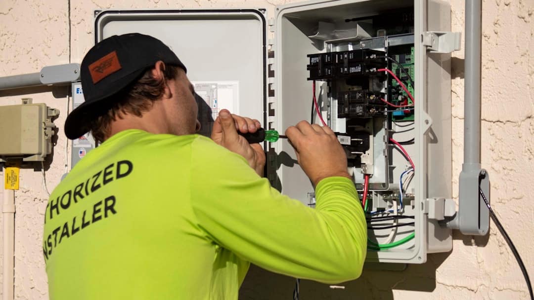
What a 1-Way Dimmer Switch Wiring Diagram Actually Shows
A 1 way dimmer switch wiring diagram is the starting point for anyone upgrading from a basic on/off switch to smooth, adjustable lighting control from a single location.
Quick answer — how to wire a 1-way dimmer switch:
- Turn off power at the circuit breaker and verify it's off with a voltage tester.
- Remove the old switch and note which wires are connected where (take a photo first).
- Connect the live feed wire to one terminal (L1 or L2) on the dimmer.
- Connect the lamp cable to the other L terminal (L1 or L2) — one terminal will remain unused.
- Connect the earth wire (with green/yellow sleeving) to the earth terminal.
- Fold wires neatly into the wall box, secure the dimmer, and restore power to test.
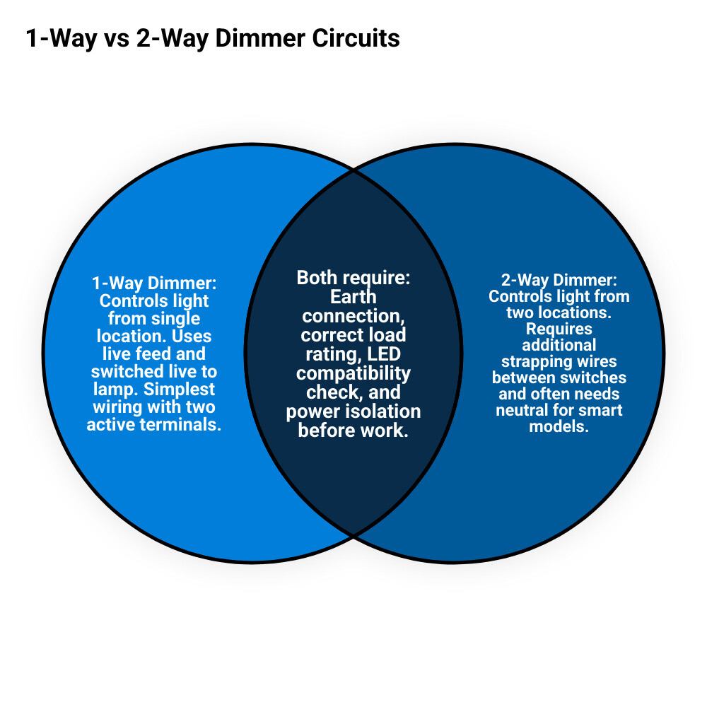
A 1-way dimmer controls a light from one switch position only. This is the simplest dimmer circuit — two wires in, one location, full control. It's different from a 2-way or 3-way setup, where the same light is controlled from multiple switch points.
Choosing the wrong setup — or wiring it incorrectly — can cause flickering, blown fuses, or a dimmer that simply won't work. According to manufacturer guidelines, dimmers must not be under-loaded or overloaded to function reliably.
I'm Ed Sartell, President of Sartell Electrical Services, and with nearly 40 years of hands-on electrical experience across Massachusetts, I've wired and troubleshot hundreds of 1-way dimmer switch installations in residential and commercial settings. In this guide, I'll walk you through everything you need to get it right the first time.
Similar topics to 1 way dimmer switch wiring diagram:
Understanding the 1-Way Dimmer Switch Wiring Diagram
At its core, a 1-way dimmer is just a single-location light control. One switch, one lighting load, one dimming point. Nice and civilized.
A typical 1 way dimmer switch wiring diagram shows four things:
- the incoming live feed
- the switched live going to the light
- the earth/ground connection
- the switch terminals
On many traditional dimmers, the terminals are marked:
- C or common
- L1
- L2
- Earth
For a 1-way installation, you usually use C and either L1 or L2. The remaining L terminal stays unused. Some products label things a little differently, so always confirm with the manufacturer instructions for that exact device.
Here is the simple rule most people need:
- one wire goes to C
- the other switched wire goes to L1 or L2
- one terminal is left empty
- earth goes to the earth terminal or back box as required
In other words, the dimmer is replacing a basic single-pole switch, not adding extra magic wires out of thin air.
If you want a broader primer before swapping devices, our guide on Dimmer Switch Wiring is a helpful companion.
Terminal identification at a glance
| Terminal | What it does | Used in 1-way setup? |
|---|---|---|
| C | Common live connection | Yes |
| L1 | Switched output or alternate control terminal | Yes, usually |
| L2 | Alternate switched terminal depending on model | Sometimes |
| Earth | Protective grounding connection | Yes |
1-way vs 2-way vs 3-way dimmers
A lot of wiring mistakes start with buying the wrong device.
| Setup | Controls light from | Typical use | Key difference |
|---|---|---|---|
| 1-way | 1 location | Bedroom, office, closet | Simplest wiring |
| 2-way | 2 locations | Staircase, hallway | One light controlled from two points |
| 3-way/intermediate | 3 or more locations | Large halls, long corridors | Adds extra switching points |
If the light is controlled by one switch only, you want a 1-way or single-pole compatible dimmer. If two switches control the same light, you do not want to guess your way through it. That is how people end up with lights that only work on Tuesdays.
Pre-Installation Safety and Compatibility
Before touching a screwdriver, stop and check the two things that matter most:
- Is the power truly off?
- Is the dimmer compatible with the load?
Both matter equally.
Safety first
Before installation, we recommend:
- turn off the breaker supplying the lighting circuit
- lock out or clearly label the breaker if possible
- verify the switch is dead with a voltage tester
- never trust a label on the panel without testing
- take a photo of the existing wiring before disconnecting anything
Basic tools usually include:
- insulated screwdriver
- voltage tester
- wire stripper/cutter
- needle-nose pliers
- electrical tape
- flashlight
- green/yellow sleeving for earth if needed
If you need a general refresher on safe switch work, read our How to Wire a Switch: Complete Wiring Guide. You can also review a consumer-oriented overview at How to Install a Dimmer Switch.
Load compatibility matters more than people think
Not every dimmer works with every lamp type. This is one of the biggest causes of flicker, buzzing, poor dimming range, or total failure.
Compatible loads depend on the dimmer model, but common categories include:
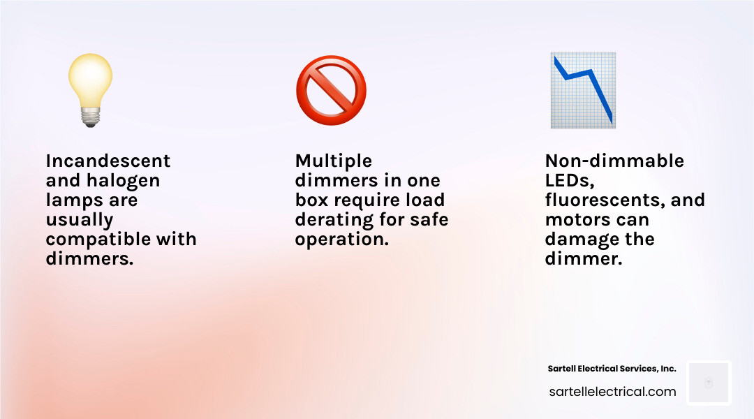
- incandescent lamps
- halogen lamps
- some dimmable LED lamps
- some low-voltage transformer-based loads when specifically rated for them
Usually not compatible unless the dimmer specifically says so:
- non-dimmable LED lamps
- fluorescent lamps
- many energy-saving lamps/CFLs
- motors and ceiling fans
- receptacles/outlets
A key manufacturer warning repeated across installation instructions is simple: using the wrong load can damage the dimmer or make it behave unpredictably.
Load ratings and derating
Always add up the total connected load before installing.
Examples from manufacturer guidance include:
- some dimmers support total lamp loads between 5W and 150W
- some older incandescent dimmers require a minimum load above 40W
- overload protection may shut the lights off if the dimmer is asked to handle too much
- under-loading can also cause flashing or unstable operation
If multiple dimmers are installed side-by-side in the same box, the rating may need to be reduced because the device runs warmer. This is called derating.
So if your dimmer says 600W by itself, that does not automatically mean 600W forever in every wall box arrangement.
One more major warning: insulation testing
Do not perform insulation resistance testing on a circuit while the dimmer is still connected. Electronic dimmers can be damaged by that testing voltage. This is a common pro-level caution that DIY articles often skip.
Step-by-Step Installation Process
Once the power is off, compatibility is confirmed, and tools are ready, the actual replacement is usually straightforward.
For more background, see our guide on How to Wire Dimmer Switch Fast by Using Simple Steps and a manufacturer-style reference at English Single Pole / 3-Way - Lutron.

Connecting the 1-way dimmer switch wiring diagram
Follow these steps carefully:
-
Isolate the power
- Switch off the breaker.
- Verify the switch has no voltage using a tester.
-
Remove the old switch faceplate
- Unscrew the faceplate.
- Remove the mounting screws holding the switch to the wall box.
- Pull the switch forward gently.
-
Identify the two switching conductors
- In a basic 1-way switch, you will usually find two active conductors on the switch.
- One is the permanent live feed.
- The other is the switched live going to the light.
- Take a photo before disconnecting anything.
-
Check the earth/ground
- Look for the bare or green/yellow earth conductor.
- If the new dimmer has a metal faceplate, this earth connection is essential.
-
Disconnect the old switch
- Loosen the terminal screws.
- Remove the conductors carefully.
- Inspect the copper ends for damage or overheating.
-
Prepare the wires
- Trim back damaged copper if needed.
- Strip insulation to the correct length for the dimmer terminal.
- Make sure no bare copper will protrude once clamped.
-
Connect the common
- Insert one conductor into the C terminal.
-
Connect the switched leg
- Insert the other conductor into L1 or L2 as specified by the dimmer instructions.
- For many 1-way dimmers, either L1 or L2 may be used with C, leaving the other terminal empty.
-
Connect the earth
- Attach the earth conductor to the earth terminal.
- If needed, use green/yellow sleeving.
- If there is a metal back box and the device instructions require it, maintain proper bonding there too.
-
Tighten terminals securely
- Tug each conductor gently to confirm it is clamped.
- No loose wires, no exposed copper, no optimism-based electrical work.
Finalizing the 1-way dimmer switch wiring diagram
Once the wiring is complete:
-
Fold wires neatly into the wall box
- Avoid sharp bends or pinched insulation.
- Arrange conductors so the dimmer sits flat.
-
Secure the dimmer
- Use the wall box screws.
- Do not overtighten and warp the faceplate.
-
Fit the faceplate
- Confirm it is level.
- On metal faceplates, re-check earthing.
-
Restore power
- Turn the breaker back on.
-
Test the dimmer
- Switch the light on.
- Check smooth dimming through the usable range.
- Listen for excessive buzzing or watch for flicker.
If you want a deeper technical overview of how dimming works electrically, our AC Dimmer Circuit Diagram article explains the principle behind the control.
Troubleshooting Common Dimmer Issues
Even a correctly wired dimmer can misbehave if the lamp type or load is wrong.
Flickering lights
Common causes include:
- non-dimmable LED bulbs
- incompatible dimmer-to-LED pairing
- load below the dimmer's minimum requirement
- loose terminal screws
- poor lamp connection at the fixture
- old bulbs near failure
What to do:
- confirm bulbs are dimmable
- verify the dimmer is rated for LED if using LED lamps
- check total load against the dimmer's minimum and maximum
- retighten terminals with power off
- try a known compatible lamp
Dimmer does not turn on
Possible causes:
- breaker still off or tripped
- line and load conductors landed on wrong terminals for that model
- failed bulb
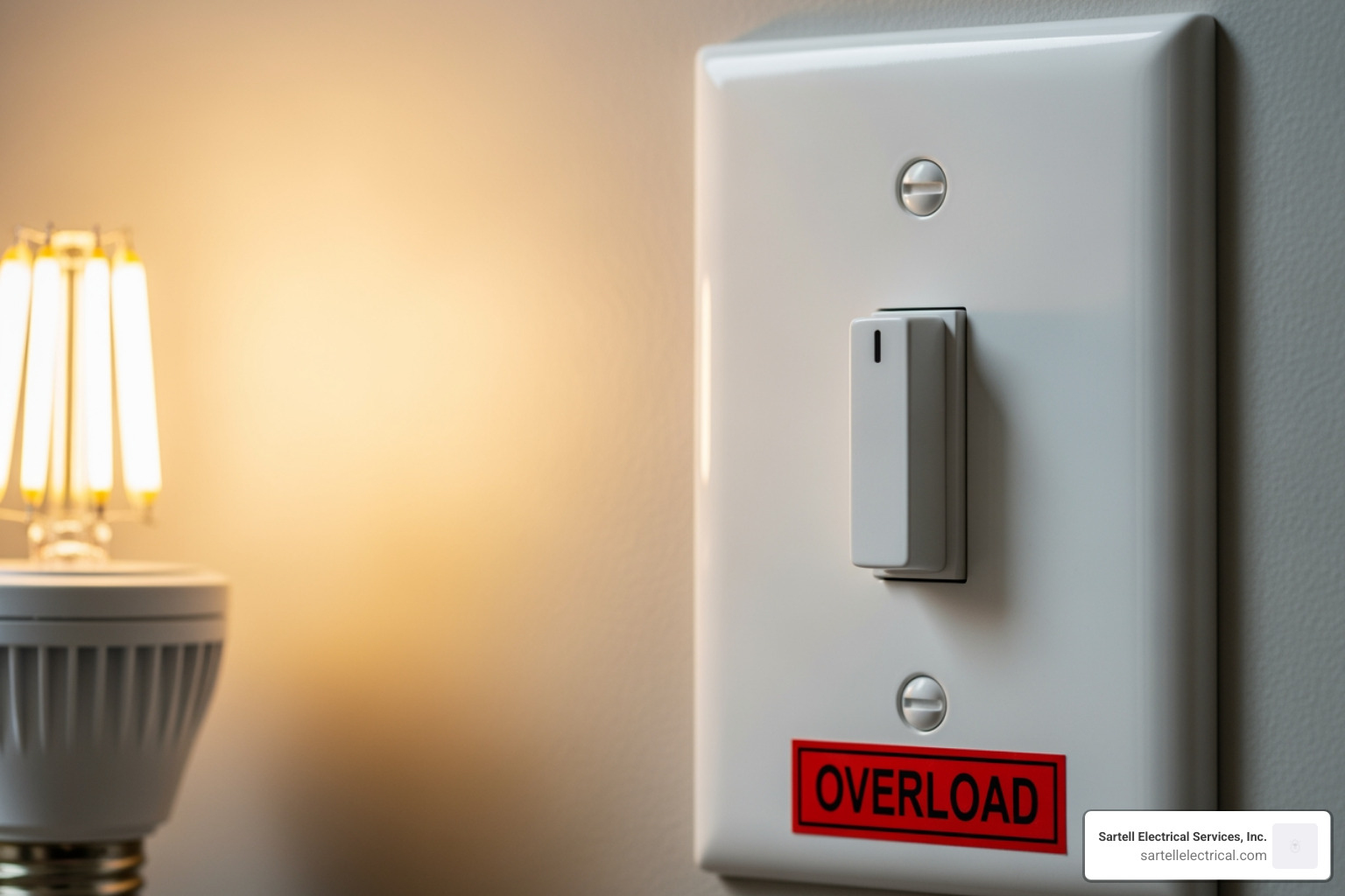
- internal dimmer protection triggered by overload
- neutral-required smart dimmer used where no neutral is present
If you are dealing with a modern electronic device, our article on The No Neutral Solution for Your 2-Wire Dimmer Switch may help explain why some dimmers work in older boxes and some do not.
Fuse blows or overload protection trips
Some dimmers include protective fusing or electronic overload shutdown. If the connected load is too high, the dimmer may switch the lights off to protect itself.
Check for:
- too many lamps on one dimmer
- wrong lamp type
- failed transformer on low-voltage lighting
- shorted wiring or damaged fixture
Under-loading and overloading
This catches many people by surprise.
- Under-loading can cause flashing, unstable output, or failure to dim properly.
- Overloading can cause shutdown, overheating, or blown protection devices.
Research-backed examples show that some dimmers need more than 40W minimum load, while others are designed to operate from 5W to 150W. The takeaway is simple: use the numbers printed on your actual device, not the numbers from your neighbor's dimmer, your memory, or a random online video.
Earth/ground mistakes
The earth is not optional decoration.
It is especially important when:
- the dimmer has a metal faceplate
- the wall box is metallic
- local code and manufacturer instructions require bonding continuity
A missing or improper ground can create shock risk and may also cause odd behavior on some electronic controls.
Frequently Asked Questions
Why are my lights flickering after installation?
The usual reasons are bulb incompatibility, low load, or loose wiring.
Start with these checks:
- Are the bulbs actually dimmable?
- Is the dimmer designed for LED, incandescent, or transformer loads?
- Is the total load above the dimmer's minimum requirement?
- Are all terminal screws tight?
- Is the bulb seated properly?
Many dimmer problems blamed on "bad wiring" are really "bad pairing." LEDs in particular can be picky.
Can I use a 1-way dimmer for a 2-way circuit?
Usually, no, not as a direct substitute.
A 1-way dimmer is for one switch location only. If your light is controlled from two switch points, you need a dimmer designed for that switching arrangement. Standard guidance for multi-location circuits is that only one device in the circuit may be a dimmer in many conventional setups, and the companion control must be appropriate for that system.
If your lighting is controlled from more than one location, these related guides are useful:
Do I need a neutral wire for a 1-way dimmer?
Sometimes yes, sometimes no.
Traditional 2-wire rotary dimmers often do not need a neutral. They are commonly installed in place of a basic switch using only the line and switched line conductors.
However, many digital and smart dimmers do require a neutral wire. Some manufacturer instructions specifically call for line, load, neutral, and ground connections even in single-pole setups.
So the answer is:
- basic analog dimmer: often no neutral required
- digital/smart dimmer: often neutral required
Never assume. Check the wiring diagram that comes with the exact model.
Conclusion
A 1 way dimmer switch wiring diagram is simple once you know what you are looking at: common, switched terminal, earth, proper load rating, and safe installation practice. The actual connection is often just two functional conductors plus ground, but the success of the job depends on the details around it, especially compatibility, grounding, and correct load sizing.
If you are replacing a standard switch in Massachusetts and want the job done safely, neatly, and up to code, we can help. At Sartell Electrical Services, Inc., we bring more than 30 years of experience to residential and commercial electrical work across Reading, Greater Boston, and surrounding communities.
For more background, visit our main guide on More info about dimmer switch wiring.
And if your wiring does not match the expected 1 way dimmer switch wiring diagram, that is your sign to pause and bring in a qualified electrician. Sometimes the smartest DIY move is knowing when not to keep unscrewing things.