How to Seamlessly Integrate Your Electrical Systems
What Is Electrical Systems Integration — and Why Does It Matter?
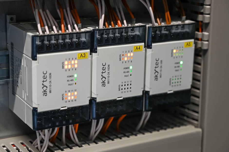
Electrical systems integration is the process of connecting and coordinating different electrical components and subsystems into one unified, efficient, and safe network.
Quick answer:
| Question | Answer |
|---|---|
| What is it? | Linking power, control, automation, and safety systems so they work together seamlessly |
| Who needs it? | Industrial facilities, commercial buildings, automotive/EV platforms, and more |
| Why does it matter? | Reduces energy waste, improves safety, cuts costs, and enables scalability |
| Key benefit | Optimized integration can reduce energy waste by up to 30% in industrial facilities |
| Main risk of skipping it | Inefficiency, safety hazards, compliance failures, and costly re-work |
Modern facilities and vehicles are no longer simple. A commercial building might run dozens of separate systems — lighting, HVAC, fire alarms, power distribution, automation — all from different manufacturers, installed at different times.
Without integration, those systems don't talk to each other. That means wasted energy, blind spots in monitoring, and serious safety risks.
With a well-executed integration strategy, everything works together. You get real-time visibility, smarter control, and a system that can grow with your operation.
I'm Ed Sartell, President of Sartell Electrical Services, and I've spent nearly four decades managing complex electrical systems integration projects across Massachusetts — from commercial builds to industrial facilities. In that time, I've seen how the right integration approach can transform a facility's safety, efficiency, and long-term reliability.
Handy electrical systems integration terms:
- electrical and instrumentation companies
- electrical & instrumentation
- industrial power distribution systems
The Core Principles of Electrical Systems Integration
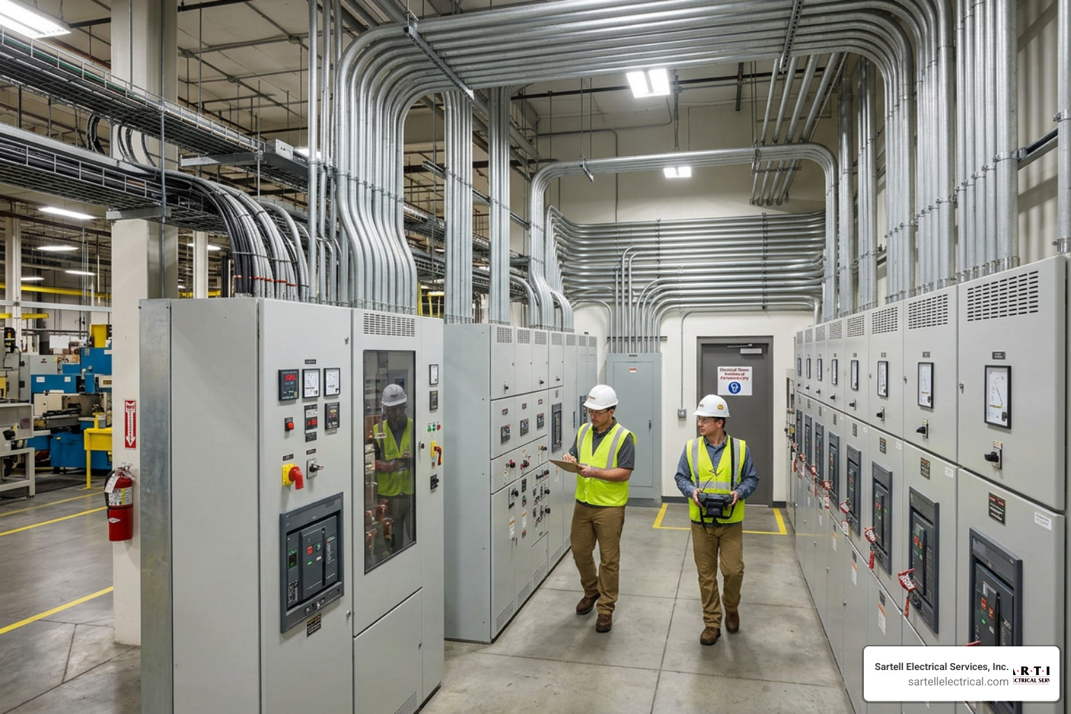
At its heart, electrical systems integration is about breaking down the walls between isolated systems. Think of a standard industrial facility: you have power distribution hardware supplying electricity, Programmable Logic Controllers (PLCs) managing machinery, and HVAC units keeping the environment stable.
When these operate as "islands of automation," they waste energy and increase maintenance overhead. Integrating them creates a cohesive, single-pane-of-glass environment where power quality analyzer data can trigger automated load-shedding commands, and HVAC systems adjust dynamically based on real-time production schedules.
According to industry data, implementing comprehensive electrical systems integration can reduce energy waste by up to 30% in industrial facilities. By optimizing power distribution and automation together, we eliminate redundant running times and minimize peak demand surcharges.
To achieve this level of optimization, you need a team that understands both high-power distribution and delicate digital controls. This is where partnering with Why Your Project Needs Electrical and Instrumentation Experts becomes vital for your project's success.
Traditional Wiring vs. Modern Multiplexed and Zonal Architectures
For decades, electrical systems relied on point-to-point wiring. If you needed to connect ten sensors to a central controller, you ran ten separate pairs of copper wires. In modern facilities and vehicles, this approach leads to incredibly heavy, complex, and fragile wiring harnesses.
Modern systems utilize multiplexed and zonal architectures to simplify physical runs and improve signal integrity.
| Feature | Traditional Point-to-Point Wiring | Modern Multiplexed / Zonal Architecture |
|---|---|---|
| Wiring Density | High; dedicated physical copper wire for every signal | Low; shared high-speed data buses (e.g., Automotive Ethernet, CAN bus) |
| Weight & Mass | Heavy; thick wire bundles increase structural loads | Light; minimized wiring mass and optimized routing |
| Scalability | Poor; adding new features requires pulling new wires | Excellent; new modules plug directly into the existing data backbone |
| Troubleshooting | Difficult; tracing broken connections through massive bundles | Simple; digital diagnostics identify exact module failures instantly |
| Signal Integrity | Vulnerable to electromagnetic interference (EMI) | High; shielded high-speed data protocols prevent data corruption |
By transitioning to a zonal architecture, we partition the system into localized zones. Each zone features its own local controller or remote power module that handles nearby devices and communicates back to the central processor via a high-speed data link. This drastically reduces wire weight, simplifies manufacturing, and ensures robust performance.
Key Benefits of Electrical Systems Integration for Modern Facilities
When you invest in a fully integrated electrical infrastructure, you are not just cleaning up your wiring closets; you are fundamentally upgrading your business's operational capabilities.
- Scalability: Integrated systems are modular. When you need to add a new production line, an EV charging station, or a solar array, you can plug them into your existing system architecture without starting from scratch.
- Enhanced Safety and Compliance: Real-time monitoring allows integrated systems to detect thermal overloads, ground faults, or phase imbalances before they trigger catastrophic failures.
- Long-Term Reliability: By reducing the physical point-to-point connections, you eliminate the most common failure points in any electrical system: physical splices and terminals.
- Advanced Performance Monitoring: Integration allows SCADA and HMI platforms to gather data from every corner of your facility, giving you actionable analytics on your energy consumption.
To explore how these benefits translate directly to your facility's bottom line, you can read more about our tailored Industrial Electrical Solutions.
Overcoming Common Challenges in Electrical Systems Integration
Integrating electrical systems is not without its hurdles. The most common obstacle we encounter is the presence of legacy equipment. Many facilities operate highly reliable machines built twenty or thirty years ago that lack modern communication ports.
To bridge this gap, we use industrial protocol gateways and intelligent electronic devices (IEDs). These tools translate older analog signals into modern digital protocols like Modbus, DNP3, or Ethernet/IP. By mapping these data points correctly, we break down information silos and bring your legacy hardware into the modern age without requiring expensive machinery replacements.
The 5 Key Phases of a Successful Integration Project

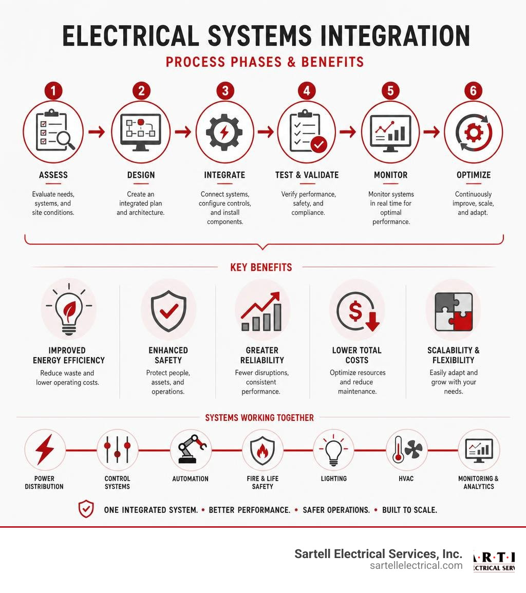
A successful integration project is never put together on the fly. It requires a rigorous, engineering-led process. At Sartell Electrical Services, we align our workflows with strict project management standards to ensure your system is optimized, safe, and delivered on schedule.
To understand how we keep complex projects on track, explore our approach to Electrical Project Management and Electrical Project Coordination.
Phase 1 & 2: Analysis, Strategic Planning, and Electrical System Design
The foundation of any integration project rests on these initial steps:
- Analysis & Strategic Planning: We begin with a comprehensive facility audit. We document all existing power distribution assets, assess network compatibility, and perform electrical loading surveys to establish an accurate baseline.
- Design & Documentation: Next, our engineers develop detailed schematics, blueprints, and data flows. We map out the physical routing, select component specifications, and design the system to meet your exact efficiency goals.
Proper planning during these phases prevents costly mid-project changes. Learn how we lay this groundwork by reading about our Electrical Pre-Construction Planning and our dedicated Electrical System Design services.
Phase 3, 4 & 5: Implementation, Commissioning, and Long-Term Maintenance
Once the designs are approved, we transition to physical integration:
- Implementation & Testing: Our field technicians install the physical infrastructure, route the cabling, and program the PLCs and HMIs. We conduct rigorous component-level testing to verify signal integrity before powering up the entire system.
- System Commissioning: During commissioning, we test the entire integrated network under real-world operating conditions. We verify safety functions, test fail-safes, and ensure 100% NEC compliance.
- Long-Term Maintenance & Reliability: Integrated systems require proactive care. We establish preventative maintenance schedules, perform thermal imaging, and run diagnostics to protect your investment and prevent unexpected downtime.
For an in-depth look at how we manage these field services, check out our Industrial Electrical Services Complete Guide.
Advanced Technologies: BCMs, RPMs, and Digital Twins
Modern integration projects leverage intelligent hardware and software to streamline power distribution and simplify control systems.
How Body Control Modules and Remote Power Modules Simplify Distribution
In both advanced vehicle platforms and complex industrial control panels, Body Control Modules (BCMs) and Remote Power Modules (RPMs) have replaced traditional fuse boxes and mechanical relays.
A BCM acts as a central computer hub, processing input signals from sensors and switches and transmitting commands across a multiplexed data link. When paired with Remote Power Modules, the physical wiring footprint drops drastically.
For example, a single RPM in a multiplexed system can control up to 80 amps of total current across six independent 20-amp outputs. Instead of routing heavy high-current wires from a dashboard switch all the way to an auxiliary load, you run a light, low-current data link to the RPM situated right next to the load. The RPM handles the heavy switching locally, reducing wiring weight, preventing voltage drops, and allowing software-defined circuit protection.
Leveraging ECAD Software and Digital Twins for Lifecycle Management
Designing these complex architectures by hand is a recipe for error. That is why modern integration relies on Electrical Computer-Aided Design (ECAD) software and digital twin technology.
A digital twin is a virtual, high-fidelity replica of your physical electrical system. By implementing a model-based electrical enterprise, design teams can simulate energy flows, test fault conditions, and verify logic before a single physical wire is cut.
Industry studies show that using these advanced design platforms can reduce design error probability by 25% and functional test time by 50%. The digital twin remains active throughout the system's life, serving as an invaluable troubleshooting tool for maintenance technicians. Platforms like the Capital Systems Integrator | Siemens enable us to maintain this digital thread from initial design all the way to active field servicing.
Safety, Compliance, and High-Voltage/Low-Voltage Integration
Integrating high-voltage (HV) power distribution with low-voltage (LV) control networks is one of the most critical safety challenges in modern electrical engineering. If high voltage leaks into your low-voltage communication lines, it will instantly destroy expensive control hardware and pose a lethal threat to operators.
Managing these risks requires a thorough understanding of system boundaries. For a complete guide on designing these robust systems safely, read our Power Distribution Systems Design Guide for Modern Industries.
Navigating NEC Standards and ISO 15288 Systems Engineering
All electrical integration work must strictly comply with the National Electrical Code (NEC) to ensure safety and maintain insurance eligibility. When we integrate complex power systems, we also utilize systems engineering frameworks like ISO 15288.
This standard ensures that safety functions, risk assessments, and Failure Modes and Effects Analyses (FMEA) are systematically applied throughout the project's lifecycle. For a deeper look into how professional engineering standards govern complex power system development, you can review the technical guidelines in Section 7 Power system development and integration.
Best Practices for Co-Locating High-Voltage and Low-Voltage Systems
When co-locating HV and LV systems inside the same enclosures or wireways, we follow strict isolation protocols:
- High-Voltage Interlock Loops (HVIL): We implement physical safety loops that automatically disconnect high-voltage power sources if an enclosure door is opened or a connector is unplugged.
- Active Discharge Circuits: These systems quickly discharge residual energy in high-capacity capacitors within seconds of a system shutdown.
- Shielding and Physical Isolation: Low-voltage data lines are routed through dedicated, shielded conduits to prevent electromagnetic interference from adjacent high-voltage lines.
- Single-Point Grounding: We establish clean, bare-metal ground connections sealed with anti-corrosion grease to prevent ground loops and shield noise.
These isolation techniques are particularly crucial in high-density environments like server farms. You can learn more about how we implement these standards in our Data Center Solutions Boston guide.
Frequently Asked Questions about Electrical Integration
How do I audit my existing facility for integration readiness?
A thorough pre-integration audit involves documenting every asset in your facility, including switchgear, panelboards, motor control centers, and existing automation controllers. We assess the physical space, check network compatibility (determining if your existing controllers can support modern Ethernet-based protocols), and review historical energy bills to pinpoint efficiency goals. Finally, we evaluate your 5-to-10-year facility growth plans to ensure the new integrated architecture is built to scale.
What are the main risks of poor electrical integration?
Poorly executed integration projects often suffer from operational downtime, signal corruption due to improper shielding, and frequent nuisance tripping of circuit breakers. In worst-case scenarios, failing to isolate high and low voltages can lead to catastrophic hardware destruction, electrical fires, and severe safety hazards for your staff.
How does systems integration support renewable energy like solar?
Integrating solar arrays, battery energy storage systems (BESS), and microgrids into your facility's main electrical system requires real-time control. Systems integration allows your facility to dynamically switch between grid power, solar generation, and battery storage based on real-time utility rates and current loads. This ensures grid stability, provides backup power during utility outages, and maximizes your return on investment in renewable energy.
Conclusion
Successfully executing an electrical systems integration project requires deep technical expertise, meticulous planning, and an unwavering commitment to safety. Whether you are upgrading an industrial manufacturing line, optimizing a commercial facility, or installing advanced low-voltage automation systems, the right integration partner makes all the difference.
At Sartell Electrical Services, Inc., we have spent over 30 years serving businesses throughout Massachusetts — including Reading, Boston, Middlesex County, Essex County, and the Greater Boston area. Our commitment to excellence, leadership, and outstanding customer service ensures that your project will be completed safely, on time, and to the highest standards.
Ready to optimize your facility's electrical infrastructure? Explore our Commercial Electrical Services or contact us today to Partner with Sartell Electrical Services on your next integration project.