Why Connecting Multiple Lights Matters for Your Project
Knowing
how to connect multiple lights to one power source is a fundamental skill for many projects, from residential hallways to commercial warehouses. Proper wiring ensures consistent brightness, simplifies troubleshooting, and meets safety code requirements.
Quick Answer: The Parallel Wiring Method
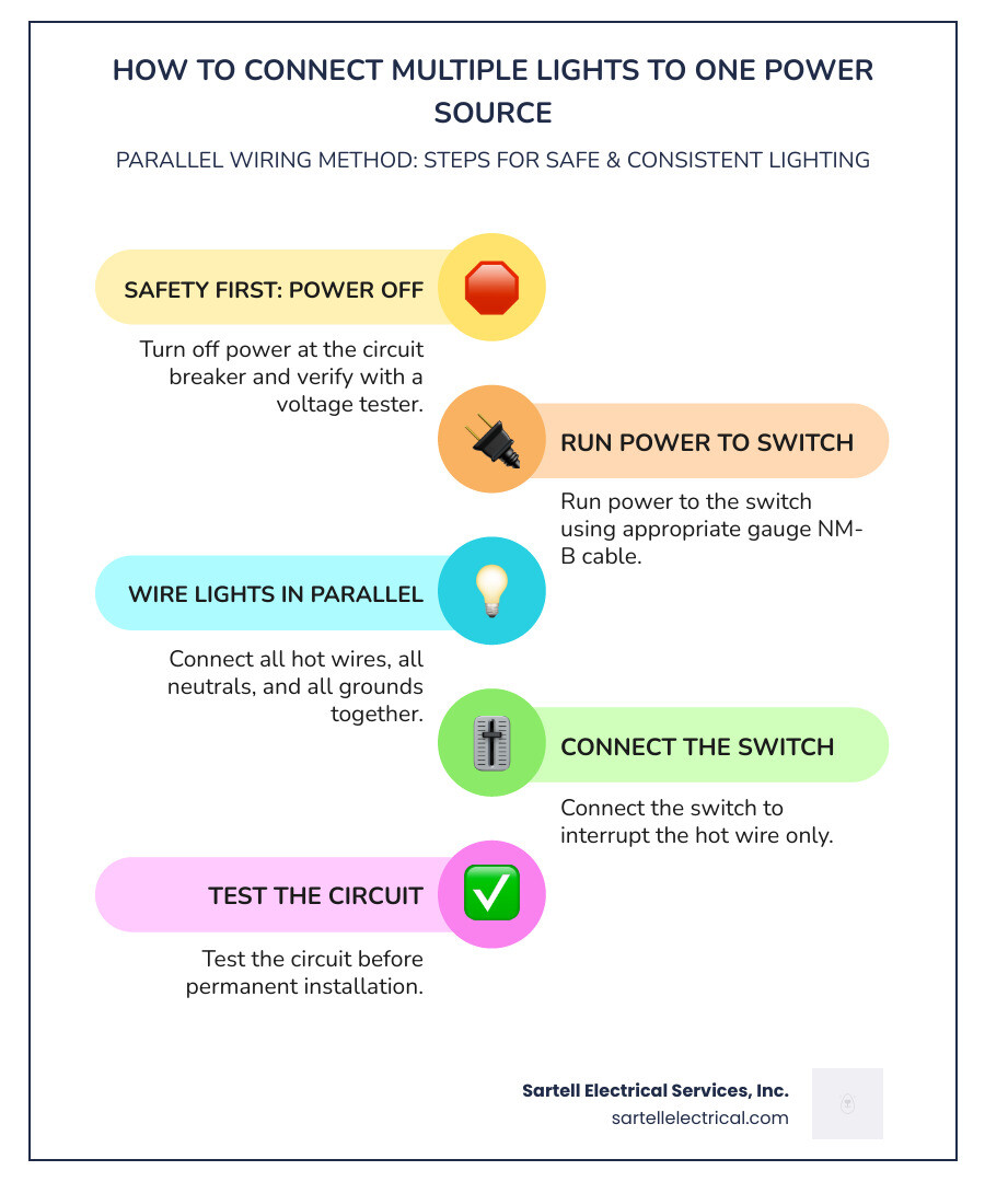
- Turn off power at the circuit breaker and verify with a voltage tester.
- Run power to the switch using the appropriate gauge NM-B cable.
- Wire lights in parallel by connecting all hot wires together, all neutrals together, and all grounds together.
- Connect the switch to interrupt the hot wire only.
- Test the circuit before permanent installation.
This method ensures each light receives full voltage (120V), maintains consistent brightness, and allows other lights to work even if one fails.
Key Requirements:
- Wire Gauge: 14/2 NM-B for 15-amp circuits, 12/2 for 20-amp circuits.
- Power Supply: Must exceed total wattage by 20% for a safety buffer.
- Code Compliance: A neutral wire is required at the switch box per NEC.
- Connection Method: Parallel wiring (never series for 120V residential).
As Ed Sartell, I've guided clients through safe electrical installations since 1985. Proper planning for connecting multiple lights prevents costly mistakes and safety hazards. Whether you're a facility manager or a contractor, understanding these fundamentals ensures your project meets performance and regulatory requirements.
Safety First: Essential Prep Before You Wire
Before any wires are exposed, prioritizing safety is non-negotiable. A successful project is a safe one. Understanding basic precautions and local regulations is the first step. For more detailed information on maintaining electrical safety in your home or business, explore our guide on
Electrical Safety Checks.
Fundamental Safety Precautions
Electrical work demands respect for its inherent dangers. The most critical step is to
turn off the power at the main circuit breaker. Don't just flip a switch; go to the panel and turn off the correct breaker. Then,
use a voltage tester to confirm the circuit is not live. This step is non-negotiable.
In commercial settings, a
lockout/tagout procedure prevents accidental re-energization. Always use
insulated tools (screwdrivers, pliers, wire strippers) and wear
proper PPE (Personal Protective Equipment) like safety glasses and insulated gloves to protect against sparks or contact with live wires. Even low voltage can be a fire hazard, so caution is key.
For any questions or concerns regarding your electrical home repairs, our team is always ready to assist. Learn more about our
Electrical Home Repair Service.
Having the right tools and materials makes all the difference. Here's a list of essentials for a multi-light installation:
- Wire strippers: For cleanly removing insulation without damaging the wire.
- Wire cutters: For snipping wires to the correct length.
- Screwdrivers: Both flathead and Phillips head.
- Voltage tester: To verify circuits are de-energized.
- Wire nuts (or appropriate connectors): To secure wire connections.
- Electrical tape: For insulating connections and marking wires.
- NM-B cable: The standard cable for residential wiring (e.g., 14/2, 12/2).
- Light fixtures: Ensure they are compatible with your power source.
Understanding Electrical Codes
Electrical codes are mandatory rules designed to prevent fires and electrocution. Massachusetts follows the National Electrical Code (NEC) but has state-specific amendments, so it's crucial to know local regulations.
Check if your project requires a
local permit. In Massachusetts, most new electrical work or significant modifications need one. Working without a permit can result in fines, insurance problems, and safety risks.
Modern codes require a
neutral wire in the switch box for most new installations. This is necessary for smart switches, dimmers, and other devices that need continuous power. Older "switch loop" wiring without a neutral is no longer permitted for new work.
Proper
junction box fill is also critical. Every electrical box has a capacity limit for wires and devices. Overfilling can cause overheating and fire hazards, so ensure your boxes are sized correctly. For a comprehensive overview of electrical wiring, including code compliance, refer to our
Building Electrical Wiring Complete Guide.
Planning Your Lighting Project
Proper planning prevents poor performance. Before you run a single cable, you need to map out your circuit, calculate your power needs, and select the right materials for the job. This ensures your lights will be bright, consistent, and safe for years to come.
Series vs. Parallel Wiring: Why Parallel is King
When connecting multiple lights, understanding the difference between series and parallel wiring is crucial. For 120V residential and commercial applications in Massachusetts,
parallel wiring is almost always the required method.
Here’s a quick comparison:
| Feature |
Series Wiring |
Parallel Wiring |
| Voltage Distribution |
Voltage is divided among lights. |
Each light receives full voltage. |
| Brightness Consistency |
Lights get dimmer down the line. |
All lights have consistent brightness. |
| Failure Impact |
If one light fails, the entire circuit goes out. |
If one light fails, the others stay on. |
| Troubleshooting Ease |
Difficult. One failed bulb breaks the whole circuit. |
Easy. Only the failed light is affected. |
For residential and commercial applications, we strongly advocate for parallel wiring. Each fixture gets the full 120 volts, ensuring consistent brightness and reliability. If one bulb fails, the others stay lit, which is why this method is standard for all modern electrical systems.
Calculating Your Electrical Load
Before adding lights, calculate the total electrical load to avoid overloading the circuit, which can trip breakers or cause fires. First, find the
total wattage by summing the wattage of all your lights. Then, calculate the
amperage using Ohm's Law:
Amps (A) = Watts (W) / Volts (V). For a 120V system, ten 60-watt bulbs (600W total) would draw 5 amps (600W / 120V).
For
power supply sizing, add a
20% safety buffer to the total wattage. For 600W of lights, use a power supply rated for at least 720W. This ensures cooler, more efficient operation and a longer lifespan.
Finally, check your
circuit breaker capacity. A standard 15-amp breaker can handle up to 1440 watts (15A x 120V x 0.80 safety rule). If your load exceeds this, you'll need another circuit. For more on your home's electrical capacity, see our
Residential Electrical Capacity Guide.
Choosing the Right Wire Gauge
The
wire gauge (thickness) is critical for safety. Using a wire that's too thin for the current can cause overheating and voltage drop, leading to dim lights and fire hazards. We use the American Wire Gauge (AWG) system, where a lower number means a thicker wire.
- For residential lighting circuits in Massachusetts:
- 14-gauge wire: Use for 15-amp circuits.
- 12-gauge wire: Required for 20-amp circuits and recommended for long runs on 15-amp circuits to minimize voltage drop.
Always check
wire gauge amp ratings. For long distances, voltage drop can still be an issue, especially with low-voltage LED strips. You can
use this voltage drop calculator to determine the right wire size for your project.
Power Source Location: Switch vs. First Fixture
A key decision is whether the main power feed enters the circuit at the switch box or the first light fixture.
- Power at the Switch: This is the most common and recommended method. Power goes to the switch box, and from there, a switched hot wire runs to the lights. This simplifies wiring and future troubleshooting.
- Power at the First Light: In some cases, power enters the first light fixture's box. A "switch loop" then runs to the switch and back. This requires 3-wire cable (e.g., 14/3 NM-B) to ensure a neutral wire is present at the switch, as mandated by modern electrical codes.
For new installations, running power to the switch first is generally more efficient and code-compliant.
How to Connect Multiple Lights to One Power Source: A Step-by-Step Guide
With your plan in place, it's time to start the installation. We will focus on the most common and recommended method: running power to the switch first and wiring the lights in parallel. For any complex installations or if you prefer professional assistance, our team offers comprehensive
Electrical Wiring Services in Boston and the surrounding Massachusetts areas.
Step 1: Run the Electrical Cable
First,
map the route for your electrical cables. You may need to drill holes and use a fish tape to pull cables through walls or ceilings.
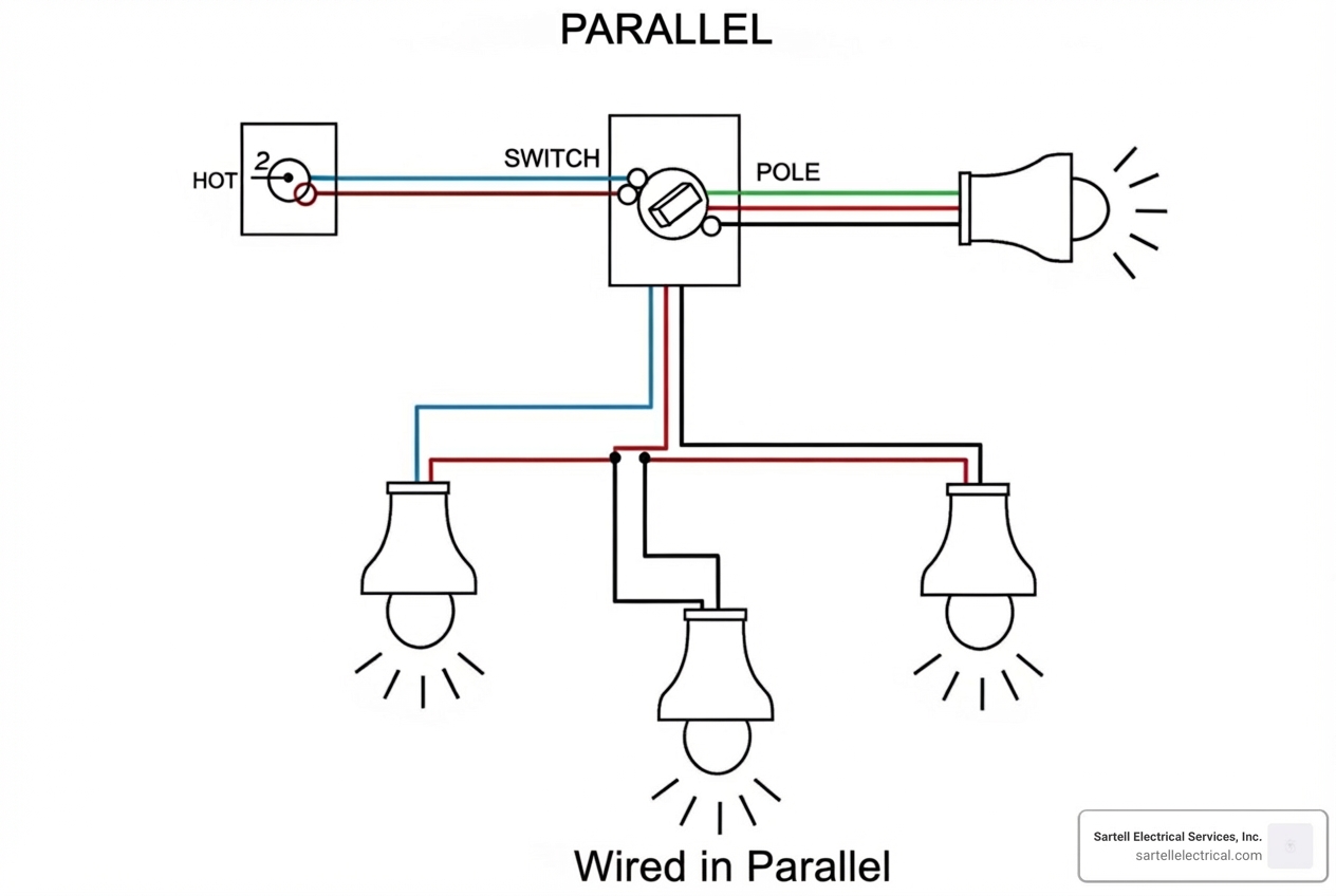
- Panel to Switch: Run a two-wire cable (14/2 or 12/2 NM-B) from the panel to the switch box to supply power.
- Switch to First Light: Run a cable from the switch box to the first light fixture. A 14/2 cable is often sufficient, but a 14/3 cable can be useful for more complex switching or if a constant hot is needed at the light.
- Between Lights: Run a two-wire cable (14/2 or 12/2 NM-B) from the first light to the second, and so on, to "daisy-chain" them in parallel.
Ensure all cables are secured and protected according to code.
Step 2: Wire the Switch Box
With the power OFF, you can wire the switch.
- Prepare Wires: Strip about 3/4 inch of insulation from the end of each wire in the switch box.
- Connect Ground Wires: Join all bare copper (ground) wires with a wire nut. Add a short "pigtail" wire from this bundle to the ground screw on the switch. If the box is metal, add another pigtail to the box.
- Connect Neutral Wires: Connect the white (neutral) wires from the power source and the cable going to the light with a wire nut. Most standard switches don't connect to the neutral, but smart switches do.
- Connect Hot Wires: Connect the incoming hot (black) wire from the power source to one terminal on the switch. Connect the hot (black) wire going to the light fixture to the other terminal. This second wire is now the "switched hot."
Ensure all wire nut connections are tight with no bare copper showing.
Step 3: Wire the Light Fixtures
Now, connect the light fixtures in parallel. Again, double-check that the power is OFF!
- Prepare Wires: In each light fixture's junction box, strip the insulation from the individual wires.
- Connect All Grounds: Join the ground wires from the incoming cable, the outgoing cable (to the next light), and the fixture itself with a wire nut. If it's a metal box, pigtail a wire to the box as well.
- Connect All Neutrals: Join all white (neutral) wires—from the incoming cable, outgoing cable, and the fixture—with a wire nut.
- Connect All Hot Wires: Join all black (hot) wires—from the incoming cable, outgoing cable, and the fixture—with a wire nut.
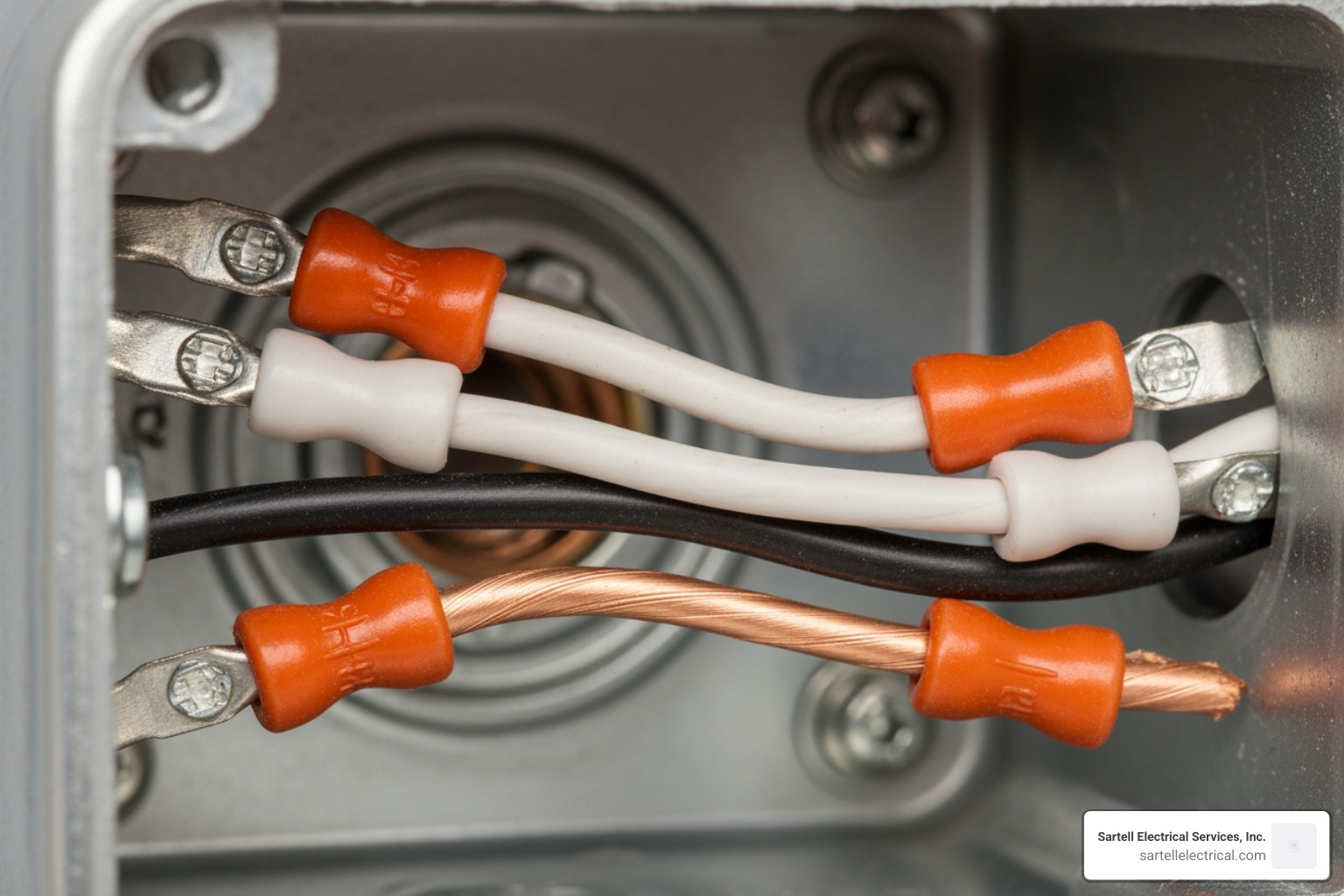
This "like-to-like" connection (ground-to-ground, neutral-to-neutral, hot-to-hot) is the essence of parallel wiring. It ensures each light gets full power. Use correctly sized wire nuts for
secure connections and use pigtails as needed to keep wiring neat.
Step 4: Install Fixtures and Test the Circuit
You're almost there! Once all wiring connections are made:
- Mount Fixtures: Carefully mount each light fixture to its junction box according to the manufacturer's instructions.
- Tuck Wires: Gently tuck all wires neatly back into the junction boxes, ensuring they are not pinched or exposed.
- Install Switch Plate: Secure the switch in its box and install the switch plate cover.
- Turn Power On: Go back to your electrical panel and turn the power back on to the circuit.
- Test Switch: Flip the switch. All your newly installed lights should illuminate!
- Test Each Light: If one light doesn't work, ensure the bulb is good. If problems persist, you'll move on to troubleshooting.
Troubleshooting and Advanced Options
Even with careful planning, you might encounter issues. This section covers common problems and how to solve them, plus ways to upgrade your new lighting circuit. For complex issues, or if you ever feel out of your depth, a
professional electrical home repair service is just a call away.
Troubleshooting When You Connect Multiple Lights to One Power Source
When your newly wired lights aren't behaving as expected, here are some common issues and what to check:
- No Lights Come On: Check for a tripped breaker, which indicates a short circuit or overload. The most common cause is a loose connection, so turn off the power and re-check all wire nuts and terminals. Also, verify your wiring against the diagram and test with a known-good bulb.
- Flickering or Dim Lights: This often points to loose connections or voltage drop from long wire runs or an undersized wire gauge. It can also be a sign of an overloaded circuit, so review your load calculation.
- Overheating Components: If any part of the circuit feels hot, turn off the power immediately. This is a fire hazard caused by an overloaded circuit or incorrect wire gauge. Re-evaluate your total wattage and wire size.
Always remember: if you're unsure, or the problem seems complex, don't hesitate to contact a licensed electrician. Safety is paramount.
Upgrading Your Circuit
Once you've successfully wired your multiple lights, you might consider some upgrades to improve functionality and energy efficiency:
- Dimmer Switches: Replace a standard switch with a dimmer to control brightness. Ensure it's compatible with your bulbs (e.g., LED-rated). For detailed guidance, see our Dimmer Switch Wiring guide.
- Smart Switches: Install smart switches for app or voice control. These typically require a neutral wire in the switch box.
- Three-Way and Four-Way Switches: To control lights from multiple locations, use three-way or four-way switches. These are more complex but add significant convenience.
- LED Fixtures: Upgrade to LED fixtures for better energy efficiency, longer lifespan, and more lighting options, which can lower your energy bills.
Frequently Asked Questions about Wiring Multiple Lights
How many lights can I put on a single 15-amp circuit?
The number of lights depends on their total wattage. A 15-amp, 120-volt circuit can support 1800 watts, but for safety, the National Electrical Code (NEC) limits continuous loads to 80% of capacity, or 1440 watts. To find the number of lights, divide 1440 by the wattage of each bulb. For example, you can have twenty-four 60-watt bulbs (1440 / 60 = 24). With energy-efficient 9-watt LEDs, you could install many more. Remember to account for all devices on the circuit, not just the new lights.
Why do my LED lights glow faintly even when the switch is off?
This "ghosting" or "phantom glow" happens when a small amount of current flows through the circuit even when the switch is off. It's common with highly sensitive LED bulbs. Causes include:
- Induced Voltage: Wires running parallel can induce a small current in each other.
- Electronic Switches: Smart switches and dimmers may leak a tiny current to power themselves.
- Improper Wiring: Older switch loops without a neutral wire can sometimes cause this.
While generally harmless, an electrician can diagnose the issue and install a component like a load resistor to fix it.
Is it mandatory to have a neutral wire in the switch box?
Yes, for most new installations in Massachusetts, a neutral wire is mandatory in the switch box. The National Electrical Code (NEC) requires it to power modern devices like smart switches, dimmers, and occupancy sensors, which need a small amount of continuous power to function. The neutral provides a return path for this current. While older homes may not have this, any new wiring or significant modification must comply with the current code.
Your Project is Complete—Or Is It Time for a Pro?
You now have the foundational knowledge for
how to connect multiple lights to one power source. For many DIYers, this is a manageable project. However, electrical work carries inherent risks, and local codes in Massachusetts can be complex. If you're in Massachusetts and feel uncertain at any stage, the licensed professionals at Sartell Electrical Services are ready to ensure your project is done safely and to the highest standard. We serve Boston, Reading, Andover, Framingham, Cambridge, and many surrounding communities in Essex, Middlesex, and Suffolk Counties, bringing over 30 years of experience to every job. For expert help with this or any lighting project, explore our
dimmer switch and lighting wiring services.