
The Hidden Risk in Your Grounding System That an Earth Continuity Test Can Reveal
An earth continuity test is a low-resistance measurement that confirms your grounding system can safely carry fault current from exposed metal parts to earth — protecting people from electric shock and equipment from fire.
Here's what you need to know at a glance:
- What it measures: Resistance between exposed metal parts and the earth connection (measured in ohms)
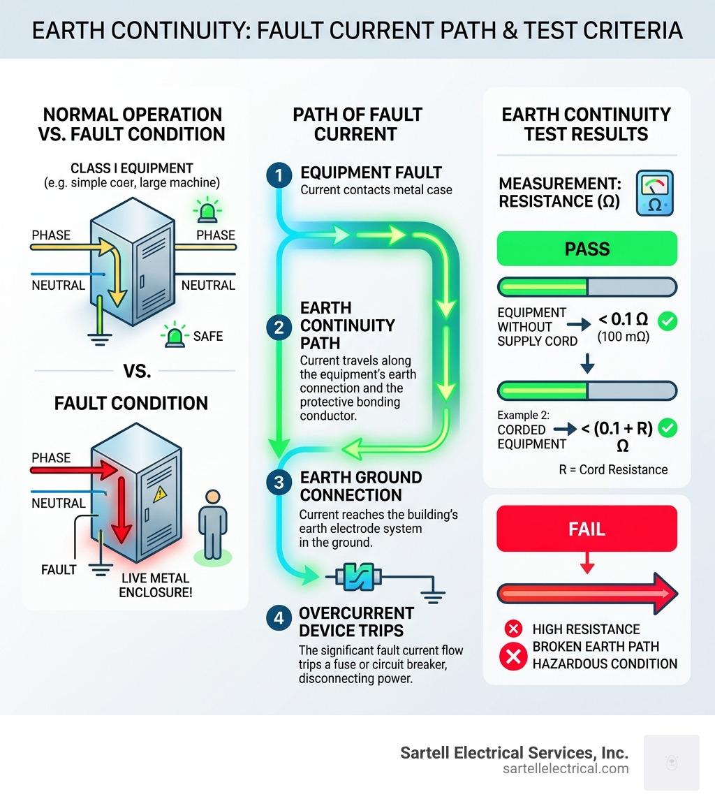
- Pass threshold: Less than 0.1 ohm (100 milliohms) for equipment without a supply cord; (0.1 + R) ohm for corded equipment, where R is the cord's resistance
- Who needs it: Any facility using Class I electrical equipment — commercial, industrial, or healthcare
- Why it matters: A broken or high-resistance earth path means fault current can't safely reach ground, turning metal enclosures into shock hazards
- Test current used: 200mA (soft test) for sensitive equipment; up to 25A (hard test) for robust appliances
- Standard: BS EN 61557-4 governs test instruments; IEC 60364-6 governs installations
Your grounding system looks fine — until it isn't. Corrosion, loose connections, and damaged conductors can silently degrade the earth path in your building's electrical system. You won't see it. You won't hear it. But under fault conditions, the consequences can be severe.
That's exactly what an earth continuity test is designed to catch — before something goes wrong.
I'm Ed Sartell, President of Sartell Electrical Services, and I've been performing and overseeing earth continuity tests on commercial and industrial facilities across Massachusetts since 1985. In the sections below, I'll walk you through everything you need to know to understand this critical safety test and what it means for your facility.
Earth continuity test word guide:
- Expert electrical safety inspection
- Annual electrical safety check
- Electrical inspection cost near me
What is an Earth Continuity Test and Why is it Essential?
At its core, an earth continuity test is a diagnostic procedure used to verify that a low-resistance path exists between the exposed metal parts of an electrical installation and the main earthing terminal. In electrical engineering, "continuity" simply means an unbroken path for electricity to flow.
When we talk about "earth continuity," we are specifically looking at the protective conductors—the green or green/yellow wires that stay silent and unused 99.9% of the time. Their only job is to provide a safe "escape route" for electricity if a fault occurs. If the insulation inside a motor or a toaster fails and touches the metal casing, that casing becomes "live." Without a solid earth connection, anyone touching that metal would complete the circuit to the ground through their body, resulting in a potentially fatal electric shock.
This test is particularly vital for Class I equipment. Unlike Class II equipment, which uses double insulation to prevent shocks, Class I equipment relies on a physical connection to the earth for safety. If that connection is high-resistance or broken, your fuses or circuit breakers won't "see" the fault quickly enough to trip, leading to sustained electrification of the chassis or, worse, overheating that causes a fire.
By performing an expert electrical safety inspection, we ensure that your facility complies with modern safety standards like BS 7671. This isn't just about ticking a box for a building inspector in Reading or Boston; it’s about making sure that if a fault happens at 2:00 AM on a Tuesday, your safety systems react exactly as they were designed to.
Technical Standards and Resistance Limits for Passing
In April 2026, the standards governing electrical testing are more rigorous than ever. To ensure accuracy, the instruments we use must comply with BS EN 61557-4. This standard dictates that the testing device must deliver a test voltage between 4V and 24V, maintain a test current of at least 200mA, and provide a resolution of 0.01Ω.
One of the most frequent questions we get from facility managers in Middlesex County is about the difference between a "Hard Test" and a "Soft Test." Choosing the right one is critical to avoid damaging sensitive electronics while still ensuring safety.
| Test Type | Current Level | Primary Use Case |
|---|---|---|
| Soft Test | 20-200mA | Sensitive IT equipment, computers, and telecommunications gear. |
| Hard Test | Up to 25A | Robust appliances like washing machines, heaters, and industrial motors. |
The "Hard Test" (often called the Earth Bond test) is generally preferred for heavy-duty equipment because it uses a higher current—typically 1.5 times the fuse rating or up to 25A for 5 to 20 seconds. This high current is designed to "stress" the connection; a single strand of wire might show continuity on a low-current multimeter, but it will burn out under a 25A load, revealing a weak and dangerous connection.
Whether we are performing a periodic electrical inspection for commercial premises or a new installation verification, these technical parameters ensure the grounding system is "beefy" enough to handle a real-world fault.
Acceptable Resistance Limits for an Earth Continuity Test
What constitutes a "pass"? The industry standard for a "good" earth connection is a resistance of less than 0.1 ohms (100 milli-ohms). However, this limit applies to the appliance or the fixed wiring itself, excluding the supply cord.
When testing corded appliances, we use the formula: (0.1 + R) Ω, where R is the resistance of the protective conductor in the supply cord. For example, a 5-meter mains lead for a standard lamp might have a resistance of 0.195 ohms. In this case, the pass limit would be 0.295 ohms.
According to Patinfo, it is vital to account for the cable's cross-sectional area (CSA) and length. A longer or thinner cable naturally has more resistance. If a reading comes back higher than expected, our team investigates whether it's due to the length of the run or a genuine problem like a loose terminal or a corroded joint.
Step-by-Step Procedure for Performing an Earth Continuity Test
Performing an earth continuity test isn't as simple as poking two probes at a metal box. It requires a systematic approach to ensure the results are accurate and the technician stays safe.

- Safe Isolation: Before any testing begins, we must isolate the circuit from the power supply. We follow strict "lock-out, tag-out" procedures to ensure no one accidentally energizes the circuit while we are working on it.
- Instrument Inspection: We check our leads and probes for damage. A frayed lead can introduce its own resistance, throwing off the entire measurement.
- Lead Nulling: This is a crucial step. We join the test leads together and use the "null" or "zero" function on the tester. This subtracts the resistance of the test leads themselves from the final reading, ensuring we only measure the resistance of the grounding path.
- Selecting the Method:
- R2 Testing: We measure the resistance of the protective conductor (CPC) from the furthest point back to the consumer unit.
- R1+R2 Method: We short the line conductor and the CPC together at the distribution board and measure the resistance at the outlet. This is the preferred method for initial verifications.
- Managing Parallel Paths: During a periodic electrical safety check, metal pipes or structural steel can create "parallel paths" for the electricity. This can result in a deceptively low resistance reading. To get an accurate measurement of the actual wire, we sometimes need to temporarily disconnect one end of the conductor.
- The "Flex" Test: For portable appliances, we gently flex the power cord during the test. If the resistance reading jumps around, it indicates internal damage to the wire that could eventually lead to a break or a fire.
Recommended Equipment for an Earth Continuity Test
To get the job done right in a commercial or industrial setting, standard hobbyist multimeters won't cut it. We utilize high-end Multifunction Testers (MFT) and dedicated PAT testers that comply with GS38 safety standards.
According to Voltimum UK, the best results come from equipment that uses Kelvin clips (four-wire sensing) or parallel-jaw clips with strong springs. These ensure a "bite" through paint or oxidation to get a true metal-to-metal connection. In high-ceiling environments, like warehouses in Andover or Lawrence, we use fiberglass insulated telescopic probes to test high-level light fittings without needing a ladder for every single point.
Specialized Applications: Solar PV and Industrial Environments
As we move further into 2026, solar PV installations have become a staple across Massachusetts, from small residential roofs to massive commercial arrays. These systems present unique challenges for earth continuity.
Solar panels are exposed to the harshest elements—extreme UV, heavy snow in Boston, and coastal salt air in Gloucester. These conditions lead to rapid corrosion of grounding clips and mounting hardware. A commercial electrical inspection for a solar site involves checking the continuity of every single frame and rack to ensure that a lightning strike or an insulation failure on a DC string has a safe path to the ground.
In industrial plant rooms, high-vibration environments can cause grounding lugs to shake loose over time. We pay special attention to heavy machinery and motor housings, where the mechanical stress on electrical connections is highest. Regular testing in these environments prevents "stray voltages" from appearing on equipment frames, which can interfere with sensitive control sensors and pose a risk to operators.
Frequently Asked Questions about Earth Continuity
What are the common causes of a failed test?
If we find a high resistance reading (anything significantly over 0.1 ohms), it's usually down to one of five culprits:
- Loose Connections: The most common issue. Screws in terminals can loosen due to thermal expansion or vibration.
- Corrosion: Rust, oxidation, or "green" copper corrosion increases resistance.
- Paint Interference: If a grounding lug is bolted onto a painted surface without the paint being scraped away first, the continuity will be poor.
- Undersized Conductors: Sometimes, during a DIY renovation or a cut-rate installation, the grounding wire used is simply too thin for the circuit's load.
- Damaged Cable Cores: A cable that has been stepped on, pinched, or kinked may have several broken internal strands.
How does testing differ between initial verification and periodic inspection?
Initial verification happens before a new system is turned on. We use the R1+R2 method to ensure every single wire was installed correctly. It is a "destructive" inspection in the sense that we are opening panels and verifying every termination.
In contrast, a commercial electrical inspection (periodic) is more about "non-destructive" verification. We might use a "long-lead" method, where we run a trailing lead from a known good earth point (like a main switchboard) and probe accessible metal parts throughout the building to ensure they are still bonded.
How often should these tests be performed in 2026?
The frequency depends on the environment and the risk level.
- Industrial/Factories: Every 1 to 3 years due to heavy use and vibration.
- Commercial Offices: Every 5 years is the standard recommendation.
- Residential Rentals: Every 5 years or at the change of occupancy.
- Solar PV Systems: We recommend an annual check of grounding integrity due to weather exposure.
While the electrical inspection cost near me is a factor for many business owners, the cost of a failed grounding system—in terms of legal liability, fire damage, or workplace injury—is infinitely higher.
Conclusion
The earth continuity test is the unsung hero of electrical safety. It doesn't make your lights brighter or your machines faster, but it is the invisible shield that keeps your employees, your tenants, and your property safe from the hidden dangers of electricity.
At Sartell Electrical Services, Inc., we’ve spent over 30 years perfecting our approach to electrical safety. Based in Reading, MA, and serving the entire Greater Boston area—from the high-tech hubs in Cambridge to the industrial parks in Woburn and the medical facilities in Boston—we bring a level of expertise and leadership that is unmatched in the region.
We don't just "pass or fail" your equipment; we provide comprehensive documentation and actionable solutions to ensure your facility is 100% compliant and safe. Whether you are managing a commercial office in Newton or an industrial plant in Peabody, our team is ready to help.
Schedule your commercial electrical inspection today and let us give you the peace of mind that comes with knowing your grounding system is rock solid.