
Why Understanding Switch Wiring Is Essential for Safe Electrical Work
A Switch Wiring Guide is your roadmap to safely connecting light switches in residential and commercial buildings. Here's what you need to know:
Quick Reference:
- Single-Pole (1-Way) Switch — Controls one light from one location using COM and L1/L2 terminals
- 2-Way Switch — Controls one light from two locations (e.g., top and bottom of stairs)
- Intermediate Switch — Enables control from three or more locations when placed between two 2-way switches
- Safety First — Always turn off power at the breaker and verify with a voltage tester before starting any wiring work
- Compliance Matters — All installations must follow BS 7671 18th Edition (UK) or Massachusetts Electrical Code standards
Whether you're replacing an old switch, upgrading to a dimmer, or installing a multi-location setup, understanding the fundamentals of switch wiring prevents electrical hazards like fires, shocks, and circuit failures. The most critical step is always interrupting power at the circuit breaker before touching any wires.
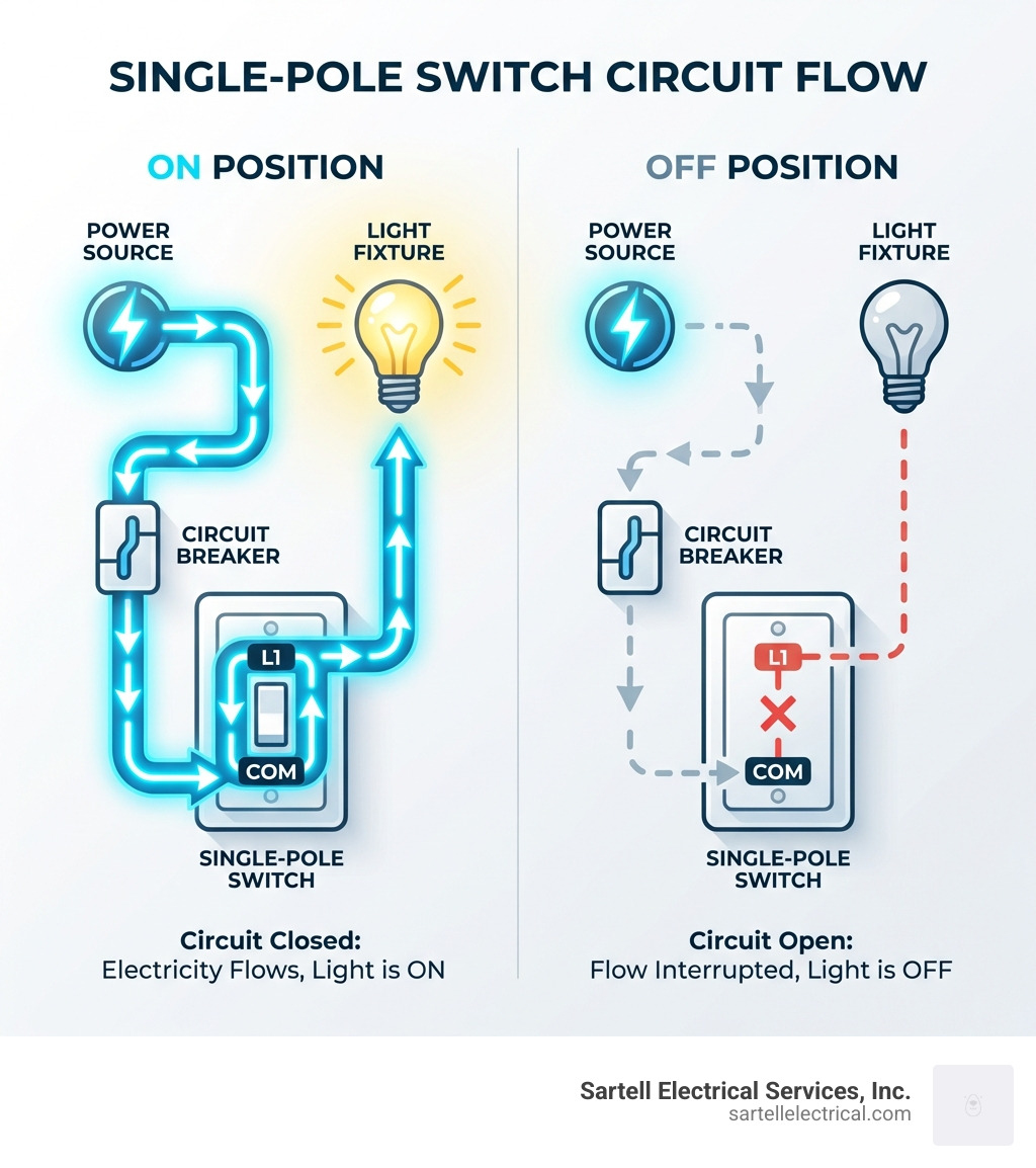
Light switches work by completing or breaking the electrical circuit between your power source and light fixture. When you flip the switch to "on," electricity flows through the hot wire to the light. When you turn it "off," the circuit is interrupted and the light goes dark. This simple mechanism relies on proper terminal connections, correctly identified wires, and secure grounding to function safely.
Modern switches use standardized terminal markings—COM (common) for the live or hot wire input, and L1/L2 for the switched output or traveller wires in multi-location setups. In the UK, wiring colors follow brown (live), blue (neutral), and green/yellow (earth) standards. In the US, you'll work with black (hot), white (neutral), and bare or green (ground) wires.
Many homeowners face the same question: Can I wire a switch myself, or should I hire a professional? The answer depends on your experience, the complexity of the circuit, and local regulations. While replacing a simple single-pole switch is accessible to DIYers who follow safety protocols, complex installations—especially those involving new circuits, multi-way switching, or commercial facilities—require the expertise of a licensed electrician to ensure code compliance and safety.
I'm Ed Sartell, and since founding Sartell Electrical Services in 1985, I've guided countless residential and commercial clients through complex electrical projects across Massachusetts, including detailed Switch Wiring Guide consultations for facilities requiring reliable, code-compliant installations. Whether you're managing a healthcare facility upgrade or coordinating a commercial build-out, understanding the fundamentals of switch wiring helps you communicate effectively with your electrical contractor and ensures your project meets critical timelines and safety standards.
Switch Wiring Guide terms to learn:
Essential Safety and Tools for Your Switch Wiring Guide
Before you even think about touching a screwdriver, we need to talk about the "Golden Rule" of electrical work: power isolation. You can’t just turn the switch to "off" and assume you're safe; you must turn off the power at the main service panel or circuit breaker.
The Essential Toolkit
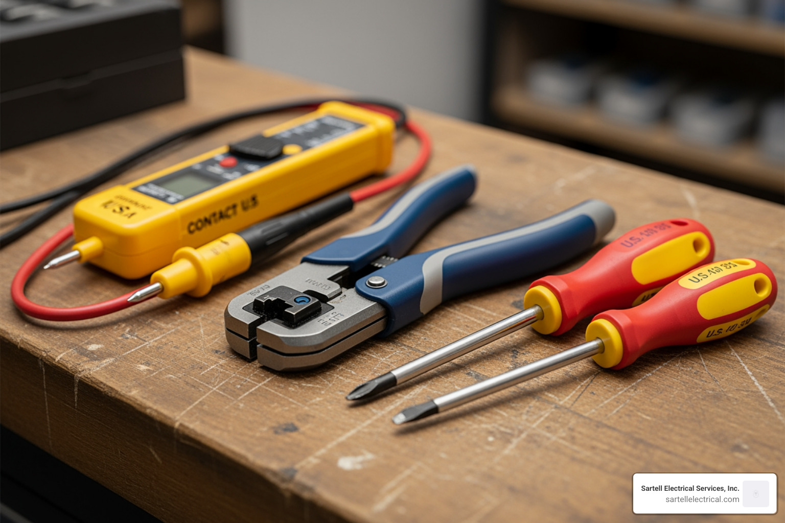
To follow this Switch Wiring Guide effectively, you'll need a specific set of tools. Using the wrong tool isn't just frustrating; it can be dangerous.
- Non-Contact Voltage Tester: This is your best friend. It detects electrical fields without you having to touch a bare wire.
- Wire Strippers: Essential for removing exactly 10mm to 3/4-inch of insulation without nicking the copper conductor.
- Insulated Screwdrivers: These protect you from accidental shocks if a circuit is unexpectedly energized.
- Pliers (Needle-nose): Great for bending wires into the perfect "U" shape for screw terminals.
- Personal Protective Equipment (PPE): This includes work gloves and rubber-soled shoes to provide an extra layer of insulation between you and the ground.
Codes and Regulations
In Massachusetts, we follow the Massachusetts Electrical Code, which is based on the National Electrical Code (NEC) but includes state-specific amendments. For our friends in the UK, the 18th Edition of the IET Wiring Regulations (BS 7671) is the legal standard.
Failing to adhere to these codes doesn't just put your safety at risk—it can invalidate your homeowner's insurance and lead to legal headaches if you ever try to sell your property. In Massachusetts, electrical permits are typically valid for 12 months, and most work requires a licensed professional to sign off.
Understanding UK and US Wiring Standards
If you're looking at a Switch Wiring Guide, you must know which "language" your wires are speaking. Colors changed over the years, so don't assume that "black" always means the same thing.
| Wire Purpose | US Standard (Modern) | UK Standard (Modern) | UK Standard (Old) |
|---|---|---|---|
| Hot / Live | Black | Brown | Red |
| Neutral | White | Blue | Black |
| Ground / Earth | Bare Copper or Green | Green/Yellow | Green |
In a standard US residential circuit, we typically use 14-gauge wire for 15-amp circuits. If you're working on a 20-amp circuit (common in kitchens), you’ll need 12-gauge wire. Using wire that is too thin for the amperage can cause the wire to overheat, potentially leading to a fire.
Step-by-Step: How to Wire a Single-Pole Light Switch
The single-pole switch is the "bread and butter" of home lighting. It’s a simple on/off mechanism that controls one light from one location.
Step 1: Power Isolation and Verification
Go to your house breaker panel and flip the breaker to the "off" position. Use your voltage tester on the wires inside the box to ensure there is zero power flowing. We like to say, "Test it, then test it again."
Step 2: Preparing the Wires
Pull the wires out of the box carefully. You should see a black wire (Hot), a white wire (Neutral), and a bare copper wire (Ground).
- Neutral Wires: In most modern switch boxes, the white neutral wires are simply tied together with a wire nut and pushed to the back. The switch itself usually doesn't use the neutral unless it's a smart switch.
- Stripping: Use your wire strippers to remove about 3/4-inch of insulation from the black wires and the ground wire.
Step 3: Terminal Connections
- Ground First: Always connect the bare copper (or green) wire to the green grounding screw first. This ensures that if there’s a fault, the electricity has a safe path to the ground.
- Hot Wires: Take your two black wires. One is the "Line" (bringing power in) and the other is the "Load" (taking power to the light). For a single-pole switch, it doesn't matter which black wire goes to which brass screw.
- Clockwise Loops: Bend the end of the wire into a "C" or "U" shape. Hook it around the screw terminal clockwise. Why clockwise? Because when you tighten the screw, the rotation will pull the wire tighter into the connection rather than pushing it out.
Identifying Terminals in a Switch Wiring Guide
When you look at the back of a switch, the labels can be confusing. Here is a quick decoder for your residential main panel wiring projects:
- COM (Common): This is where the permanent live power enters the switch.
- L1: This is the "Switched Live." When the switch is "on," power flows from COM to L1 to turn on the light.
- L2: Used in 2-way switching. If you're only doing 1-way switching, you can ignore this terminal.
- Green Screw: Reserved strictly for the ground wire.
Advanced Configurations: 2-Way and Intermediate Switching
Ever wondered how you can turn a hallway light on at one end and off at the other? That’s 2-way switching. If you add a third switch in the middle, that’s an intermediate switch.
How 2-Way Switching Works
A 2-way circuit uses "traveller" wires to pass the "hot" signal between two different switches.
- Switch A: The "Line" (power in) goes to the COM terminal.
- Switch B: The "Load" (wire to the light) goes to the COM terminal.
- The Bridge: You connect the L1 of Switch A to the L1 of Switch B, and the L2 of Switch A to the L2 of Switch B. These are your travellers.
Intermediate Switching
If you have a very long hallway or a staircase with three floors, you’ll need an intermediate switch between your two 2-way switches. The intermediate switch essentially "crosses" the traveller wires to toggle the circuit state from a third location. Learning how to connect multiple light switches is a game-changer for large Massachusetts homes or commercial offices in Boston.
Special Considerations for Dimmer Switch Wiring Guide
Installing a dimmer-switch-wiring setup adds a layer of complexity.
- LED Compatibility: Not all dimmers work with all LED bulbs. You must use a "trailing edge" dimmer for most modern LEDs to prevent flickering.
- De-rating: If a dimmer is rated for 400W of incandescent bulbs, it might only be rated for 120W of LEDs. Always check the manufacturer's specs (like the Varilight V-Pro).
- 2-Way Dimming: You generally cannot have two traditional rotary dimmers on the same circuit—they’ll fight each other like "crossing the beams" in Ghostbusters! Instead, use one master dimmer and one "slave" unit or a "dummy" switch.
For a deeper dive into multi-location dimming, check out our guide on installing your 3-way dimmer switch like a pro.
Troubleshooting and Common Wiring Mistakes
Even with a great Switch Wiring Guide, things can go wrong. Here are the "usual suspects" we see in the field:
- Flickering Lights: Often caused by a loose connection. If a wire isn't snug under the screw terminal, the electricity "arcs," causing the light to flicker and the terminal to heat up.
- "Backstabber" Connectors: Many DIY-grade switches have small holes in the back where you just push the wire in. Pro electricians call these "backstabbers" because they are prone to failing over time. We always recommend using the side screw terminals for a secure, long-lasting connection.
- Lights Staying On: If you've wired a 2-way switch and the light won't turn off, you likely swapped a traveller wire with the common wire.
- Overheating: If the switch plate feels warm to the touch, you might be exceeding the switch's amperage or wattage rating. Standard switches are usually 10 amps, but dimmers have much lower thresholds.
- Improper Grounding: Never skip the ground wire. In the event of a short circuit, the metal parts of the switch could become electrified, giving a nasty shock to anyone who touches it.
If you've tried these fixes and your lights are still acting up, it's time to contact a professional. Electrical issues can sometimes be symptoms of larger problems in your home's wiring, especially in older Massachusetts properties.
Frequently Asked Questions about Switch Wiring
What is the difference between a 1-way, 2-way, and intermediate switch?
- 1-Way: One switch controls one light. It has two terminals (COM and L1).
- 2-Way: Two switches control one light. It has three terminals (COM, L1, and L2).
- Intermediate: Used when you need three or more switches for one light. It usually has four terminals and sits between two 2-way switches.
Can I use a 2-way switch for a 1-way circuit?
Yes! In fact, most manufacturers today only make 2-way switches because they work perfectly fine for 1-way circuits. You simply connect your wires to COM and L1, and leave the L2 terminal empty. It’s a great way to save money and reduce the number of spare parts you need to keep on hand.
When should I hire a professional electrician?
While replacing a broken rocker switch is a common DIY task, you should call us at Sartell Electrical Services if:
- You are installing a brand-new circuit.
- You are working with a commercial or industrial high-voltage system.
- Your home has "knob and tube" or aluminum wiring.
- You aren't 100% confident in your ability to follow the AC dimmer circuit diagram.
- You need to ensure compliance with the latest Massachusetts Electrical Code for a permit or insurance purposes.
Conclusion
Mastering the basics of a Switch Wiring Guide empowers you to maintain and upgrade your home’s lighting with confidence. From understanding the difference between a COM and L1 terminal to knowing how to safely isolate power, these skills are the foundation of electrical safety. However, electricity is unforgiving. A small mistake can lead to significant property damage or personal injury.
At Sartell Electrical Services, Inc., we’ve spent over 30 years providing top-tier electrical solutions to our neighbors in Reading, MA, and throughout the Greater Boston area. Whether you're in Medford, Cambridge, or over in Andover, our team is committed to excellence and customer service. We handle everything from simple residential repairs to complex industrial telecom installations.
If you’re feeling overwhelmed by a multi-way switching project or want to ensure your new smart dimmers are installed to code, don't hesitate to reach out. Schedule a professional dimmer switch installation with us today and rest easy knowing your home is in expert hands. We're here to help you keep the lights on—safely and efficiently.